Tutorial written by Ricebug. Mirrored here for archival purposes. Note his example file/textures have been lost to time, however all of the images for this tutorial were preserved.
Designing An Aircraft
Based on Q3Radiant Build 201
Part 1 in a Series, by Ricebug
Most of my tutorials have dealt with how to use Q3Radiant, without any real projects to sink our teeth into. After giving it much thought, I've decided to go ahead and do a series of tutes that will hopefully try and cover an entire project. And since I'm an aircraft maintenance puke in my real life in the U.S. Air Force, what better project to cover than that of an aircraft maintenance hangar, complete with equipment and a large, cargo-type weapons system. (The USAF likes to call its aircraft "weapons systems." The term "airplane" is strictly taboo.)
We'll be using some custom textures; we're going to get into extensive prefab work; a hangar will have to be built, obviously, complete with operating doors. Last but not least, thought will have to go into the "battle" aspect of such an environment.
1. Building the Aircraft: The Center Fuselage
Hopefully, you're using the latest version of Q3Radiant. As of this writing, its up to Build 201. I'm going to also assume that you have a fundamental knowledge of the editor. At minimum, you should be familiar with mesh and patch control, how to place and manipulate entities, and other basics.
1. Pull down the Textures menu and select base_wall/patch10. Press 7 on the keyboard to set your grid snap to 64. Ctrl-Tab to the Top view, drag out a brush 256x256. Flip to the Side view and stretch it on either end so until it's 512 units long.
2. With the brush still selected, go to the Curve menu and select Cylinder. Then rotate it by pressing the ![]() button.
button.
3. Press CTRL-T to bring up the Thicken Patch dialogue. Since our fuselage will be mated to other sections, we really don't need to worry about seams, but let's keep things tidy. Go ahead and change the amount from 8 to 2.
4. De-select everything and Shift-Click on the center of the cylinder. Drag the inner mesh somewhere out of the way, since it's not needed right now.
5. For the floor deck, load the common/nodraw shader. Now flip to the Top view and drag out a 512 x 256 brush. Flip to the Front view and size the grid to '4' by pressing 3 on the keyboard. Resize this brush so it looks like the screenshot here to the right.
To clear out the Texture Preview window of unneeded shaders, go to the Textures menu and select Flush and Reload Shaders.
Select the base_trim shader set and texture the ends of this brush with xian_dm3padwall_x and the floor with xian_dm3padwall_y.
 6. Turn on the clipper by pressing X and cut away the parts of this brush as shown in the picture to our left. Use Ctrl-Return to flip the clipping plane if you find yourself snipping away the wrong half of the brush.
7. Once you clip the brush into a reasonable shape, go back and adjust the edge/vertex points by dragging and adjusting them with a fine grid setting of 1. You may find that some control points respond better with Edge manipulation, while others are more compliant with Vertex mode. Zoom real close to adjust them and keep your eye on the 3D preview window. If the brush leaps out of bounds, press Ctrl-Z to undo and retry with a different mode.
8. Save your work, naming it acft. (Radiant will automatically add the .map filename extension.)
9. For the fuselage's ceiling, do the same thing as you did with the floor, except make the brush only 32 units tall. I used base_trim/spiderbit4 for the ends of this brush and base_wall/metfloor_block3 for the "ceiling" side.
10. Remember the inner mesh that we dragged out of the way back in Step 4? Let's apply the base_wall/redpad texture to it and drag it back inside the other cylinder. To make things more interesting shrink this mesh to one-third its length, and clone it (Spacebar). Place the clone at the other end of the fuselage so that you end up with a cylinder at each end as shown here in the screenshot.
11. Clone the mesh again and re-size it so that it fits between the other meshes. Apply the base_wall/bluemetalsupport2 to it. Bring up the Surface Inspector and click the Natural button.
2. Building the Aircraft: The Forward Fuselage
The forward fuselage will be almost the same as the center, except in two pieces. One will provide a crew entry door and the other piece will be the nose of the aircraft.
1. Save your work and once again, Flush and Reload Shaders to get rid of any unnecessary textures.
2. Re-size the floor and ceiling brushes so that one end juts out 128 units from the end of what will be the "front" of the aircraft. Here's a screenshot:
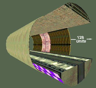
3. Select the patch10 texture. In the Top view, drag out a 256-square brush and make it 128 units tall.
4. Turn this into an endcap (Curve/Endcap)
5. Rotate it by clicking once on the ![]() button.
button.
6. Flip to the Front view. By clicking ABOVE the selected endcap, drag downward until the mesh is halfway and in alignment to the fuselage. Press Ctrl-I to invert the mesh. You should have what amounts to a lower half of a fuselage which is 128 units long.
7. Still in Front view mode, press V and zoom in very close to the RIGHT side of the mesh. Looking at the screenshot below, drag the two vertices until the mesh is re-positioned to allow for the doorway.
Note how the 3D preview shows the mesh's new position to allow for our crew entry door.
8. Repeat steps 3 thru 7 and do the same thing to make the top half of the forward fuselage. The only difference will be having to click the ![]() twice. I found that an initial grid setting of 32 made it easier to drag the two vertices, with minor adjustments made by decreasing it down to '2'.
twice. I found that an initial grid setting of 32 made it easier to drag the two vertices, with minor adjustments made by decreasing it down to '2'.
9. Once the top is in place, select the bottom patch and thicken it, with a seam size of '2'. Repeat the step for the upper patch. Isolate the new inner meshes and texture the top mesh with the redcap texture and the bottom mesh with bluemetalsupport.
10. For the nose, select the patch10 texture and drag out a 256-cube brush.
11. Turn this into a cylinder and rotate it. Press Shift-C to give it have a Normal Cap.
12. Since we're not going to construct a flight deck, we'll apply a "door" texture to make the player think there's one behind it.
Tab until the endcap which is mated to the center fuselage is highlighted and apply my custom shader, hangar/door. Adjust the texture's orientation using the Shift-Cursor keys or by Alt-Clicking-Dragging until the door texture is centered. Mine came out looking like the screenshot.
A custom "door" texture applied. (Made with Wally)
13. The opposite end cap will become the nose of our aircraft. So Click and Tab until the cap is selected. Press V to enter Vertex Mode. Position the camera so you're looking at the 3D preview window and right at the endcap. You should see 4 green dots and 4 purple dots forming a square around the cap. In the center of the endcap there should be a purple dot. Click on this dot in the 3D preview window and drag it downward.
14. Now you can go to the side view in the main editing window and drag this vertex until you get the nose shape similar to the one shown here to the left.
15. Don't worry about the lack of cockpit windows--we'll fix that in a later tutorial.
3. Building the Aircraft: The Aft Fuselage
1. Click on the patch10 texture and create a 256-cube brush.
2. Make it into a bevel and rotate/position it so that it's butted against the end of the center fuselage.
3. Go to the Side view. Press V. Drag the right vertex up 64 units as shown here.
4. The cargo doors would be too short on an aircraft of this size, so let's drag the mesh out to a length of 448 units.
5. Thicken this also, with a seam value of 2. Texture the inside mesh with redcap.
6. To make the clamshell doors, drag out a brush in the Top view 128x128 and rotate until the door is in position. Then, re-size it in the Front view so that it's 64 units wide.
7. Clone this door and flip/rotate to make the other door, and then thicken and texture them both.
8. For the loading ramp, make a simple brush with an angled lip as shown below. Also, lengthen the brush that makes up the center fuselage ceiling so that it's even with the edge of the cargo ramp.
9. Obviously, the clamshell doors require some sort of supporting hydraulics to make them appear more attached to the aircraft. First, make a beam 16 x 16 x 384, texturing it with the base_support/basic1_1. Place this beam up in the ceiling and clone it and position it so they look like the ones here. Climb up on top of the aircraft in 3D preview mode to make sure the beams aren't sticking through the body of the aircraft.

10. Now make two brushes that will be the hydraulic lifts for the ramp. Use the basic1_1 for the two ends and base_trim/tin for the shaft.
Front view of hydraulic assembly

Once done, clone and flip it on the X axis. Adjustments may have to be made to angle the lower block to match the angle of the ramp, as shown here:

11. For the tail section, drag out a brush 256 x 128 in the Top view and 64 units wide in the Side view.
12. Go to the Curve menu and select Cone.
13. Rotate on the X axis ![]() and butt it against the fuselage.
and butt it against the fuselage.
14. Click and drag the bottom to stretch it by 64 units to make it 128 units tall.
15. Press V and drag the cone's apex out as shown here. Put an endcap on it and apply the base_trim/bridgesupport1e to the cap.
4. Building the Aircraft: The Landing Gears
1. For the main gear doors, drag out a 64x32 brush and turn it into a simple mesh. Rotate/flip so that it sits beneath the center fuselage but somewhat on the side, like so:
For detail work, open up a second copy of Q3Radiant. This gives you an uncluttered workspace where you can move your stuff back and forth between editors.
2. Open up another copy of Radiant. Now make an 8 x 8 x 96 brush, texturing it with base_ceiling/metceil1d.
3. Click on the base_support/cable texture and make a capped cylinder mesh 64 units in diameter and 32 units thick. Tab to the tire sidewalls and apply the custom texture hangar/wheel. Call up the Surface Inspector to FIT this texture to the endcaps.
4. Clone this tire and put it on the other side of the strut, so that the latter is between the two tires.
5. Now select everything and and ungroup the two tires and strut. (Right-click/Ungroup entity) With everything still selected, turn this assembly into a func_static.
6. With your gear assembly still selected, press Ctrl-C to copy it. Alt-Tab to the other editor with the aircraft and position it where you want. Clone 3 of the landing gears and place them under the aircraft. Place another two near the nose for our nose gear.
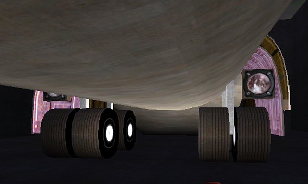
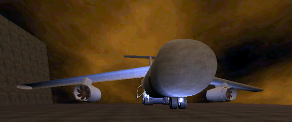
Main landing gears supporting our cargo aircraft
We made the tire assemblies into func_statics to decrease VIS times. In the Quake2 renderer, we would have done the same thing by turning a prefab into a func_wall. In Q3 editing, a func_static can serve the same purpose. Doing so makes the VISibility engine treat the prefab as though it did not exist.
5. Building the Aircraft: The Wings & Empennage
1. Once again, we'll be creating the wings in a separate copy of the editor. After selecting the patch10 texture, flip to the Top view and create a brush 384 x 64. Go to the Front view and make this brush 1024 units tall. Turn it into a cylinder and rotate it to "lay it down" in the top view. Remember, this will be a wing, so orient it as shown in the screenshot below.
Looking at the cylinder from the end view.
2. Press 5 on the keyboard to get a grid snap of 16. Enter Vertex mode and drag the lower right vertex over 128 units as shown here.
3. Drag the center right vertex down 32 units.
4. Drag the upper right vertex over 128 units.
5. Drag the top center vertex over 64 units.
6. Flip to the Top view, press V, hold down the SHIFT key, and click TWICE on a corner vertex to make the ones on the short side turn blue.
7. With these 3 vertexes selected (blue), go to the Selection menu and choose Scale. Enter .5 in the Y and Z input fields. Click OK.
8. De-select and re-select these same blue vertex points and drag them all down 96 units (3 grid snaps).
9. Now grab the 3 vertexes in the wing's center and drag them down until the trailing edge of the wing is straight, as shown below:
10. De-select the wing and re-select it. Press Shift-C to cap it.
11. Tab until the cap on the inboard (widest) side of the wing is selected. Delete it.
12. Select the wing again and Tab until the other cap is selected. Zoom in fairly close with your camera in the 3D preview window.
13. Press V. In the 3D preview window, click on the center purple control point and drag it down slightly so that it presents itself in the main editing window.
14. With a grid snap of 16, you want to click and drag this vertex out until you achieve the approximate shape of a wing tip.
15. The last thing that needs to be done is to rotate (R + Left-Click + Drag) the wing slightly so that it will "droop" or hang down. Wings on large aircraft do not stick out in a perfectly straight line. Rotate the brush accordingly. Once you're satisfied with your work, copy the wing into the editor containing the aircraft and clone/flip it.
16. For the empennage (tail section) create 3 delta (triangle-shaped) brushes and glue them to the tail like so:
The T-tail horizontal stabilizer applied as another func_static.
If you really want to go to the trouble of building this section like we did the wings, go ahead. Since it sits so high above the player however, it may not be worth the extra effort.
6. Building the Aircraft: The Engines
1. Before we construct an engine, save your work. Once, again, we'll work with two copies of Q3Radiant running, keeping the aircraft in one editor while creating the engine in another.
2. We will create our primary brush in the editor containing the aircraft, since we first want to get a rough estimate of the engine's size and position in relationship to the wing.
3. Create a brush 256 units long and 128 units square, positioning it where one of the engines will be. (This aircraft will sport only two engines.)
4. Press ![]() and turn it into a cylinder. Press
and turn it into a cylinder. Press ![]() again to rotate it back.
again to rotate it back.
5. Position this cylinder where you want it underneath the wing, maintaining about 32 units between it and the wing. This will allow for a pylon. (A pylon is an attachment holding the engine to the wing.)
6. Press Shift-C to cap it. Copy the selected group and then delete it. Paste it into the other copy of Q3Radiant, which should be empty.
Since Radiant has no "cut" function, you have to get used to copying and then deleting the item by using the Backspace key. CTRL-V will paste it. If you do screw something up, keep pressing CTRL-Z to undo the mistake.
7. Go the YZ Side view and select only the central mesh. Press V and then Shift-Click to choose the 3 vertices running up the center.
8. Bring up the Scale dialogue again and enter 1.2 in all 3 fields. This will give our engine body a realistic bulge in the center.
9. Select the newly bulged mesh and press CTRL-T to thicken it. Since this assembly already has endcaps, uncheck Seams. What we've just done is add an inner shell to our cylinder, effectively making it double-sided. The reason for this will become clear later.
10. Select the base_trim/tin texture and put a cylinder on the rear of the engine. Thicken it with the default of 8 seams.
11. Select the base_support/flat1_1 texture and create a cone 128 units cubed. Place it inside the rear of the engine as shown here.
12. Before adding the front ring cowl, texture the front cap of the main cylinder with the sfx/fan shader. Use the Surface Inspector to FIT it. Since this shader has a transparent surfaceparm, you will be able to see through into the engine, which is why we thickened the cylinder back in step 9.
13. As we did with the rear of the engine, add a cylinder to the front. After positioning it to the front of the main engine body, press V and select the center vertices. Scale these with a value of .95 on all three axes. Now select the front vertices and scale these to .9. This will give the ring cowling a tapered appearance.
14. Thicken the ring cowling with the default of 8 seams.
15. Create a 16-unit-thick brush and add a pylon to your engine like so:
16. Once you're satisfied with your engine, save it as engine into the baseq3/maps directory.
17. Close this copy of the editor and return to the aircraft.
18. Now go to File/Load and select engine.map. The engine will load beneath the wing in the exact position you created it.
19. With the engine group still selected, do an Ungroup Entity, followed immediately by a func/func_static.
20. Clone the engine, press 7 to snap the grid to 64, and move the clone to the other wing.
Using the Load command allows you to insert map files into the editor. Once they're loaded, they remain selected so that you can position them where needed. This is a great tool for building complicated maps section-by-section, or, if you are doing a project with several people. Each person can work on his or her section, and then they can all be Loaded into the editor to make one map. For all intents and purposes, it's the same as Load Prefab but without the directory path definition.
21. As a finishing touch, add a target_speaker and use the world/fan4 sound for your idling turbofans.
We need to spend more time tweaking this aircraft. One thing it needs is a better exterior texture and some identification markings. The engine fans reveal an empty shell behind them. It needs some doors, lights, and so forth. We'll cover all these things in the next tutorial.
Slap a quick box around your aircraft, throw a player_start in, use Q3Build to compile, and go check out your cargo aircraft. You can grab the .map file here, if you didn't follow along.