Tutorial written by Eutectic and Ricebug. Mirrored here for archival purposes. Note his example file/textures have been lost to time, however all of the images for this tutorial were preserved.
Introduction
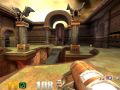
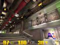
In this tutorial, I'll explain how shaders work using multiple textures to provide some of the effects seen in Quake 3: Arena. For our example, we'll look at textures/sfx/border11c, which is found in the sfx.shader file. This is a shader used for wall borders with a cool purple stripe that races horizontally across it's entire width. Here's how it looks in the game:
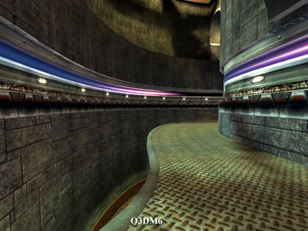 This purple-blue stripe races around the hallways in Q3DM6.
Shader Overview
Here's the actual shader script:
By doing a basic initial breakdown of the shader script, we can tell right away that are 3 texture map stages this shader. So let's extract these 3 textures from the textures/base_trim internal folder of the pak0.pk3 file and see what they look like:
border11c_pulse1b.jpg
Here, you may have noticed that although the script refers to TGA files, the actual textures in the pak0.pk3 are really JPG files! How can this be?...
Very simple. Quake III Arena shaders can use both TGA and JPG textures. The way it works is that the game tries to find a TGA image first as stated in the shader script. If it doesn't find one, it will automatically look for a JPG file of the same name instead. This is why shaders always refer to TGA's although the actual texture can be a TGA or a JPG.
You can create your own custom textures in TGA or JPG format as long as it's 24-bit. Also, TGA's can be either 24 or 32-bit (if there's an alpha channel). For this reason, when making your own custom textures, make sure you don't save TGA's in 16-bit format otherwise the game and the editor won't be able to read them.
General Keywords
q3map_surfacelight 300
q3map_lightimage textures/base_trim/border11c_pulse1.tga
qer_editorimage textures/base_trim/border11c.tga
Although the general keywords of this shader are not really at the heart of the subject of this tutorial, I'd like to draw a parentheses here to explain a fact not widely know about shaders which emit light such as this one. If you're only interested in knowing how the flickering and scrolling effects of this shader work, you can just skip to the next section. But if you intend to work with or create shaders which emit surface light, I really think you should read on.
This particular shader is a perfect example to illustrate what I mean. Let's take a look at the first line of the general keywords:
q3map_surfacelight 300
This tells the q3map compiler that this shader will emit surface light and that the intensity value of that light is 300. But the compiler also needs another piece of information before it can begin calculating emitted light for those surfaces: light color. This information is normally provided by the next keyword:
q3map_lightimage textures/base_trim/border11c_pulse1.tga
The q3map compiler will use the average color of this texture for the average light color. But wait!... There is no texture named base_trim/border11c_pulse1.tga or base_trim/border11c_pulse1.jpg in the pak0.pk3 file! So how will the compiler know what light color to use? Ah! This is where the next keyword in the shader comes in:
qer_editorimage textures/base_trim/border11c.tga
If the image specified in the q3map_lightimage keyword doesn't exist, the compiler will automatically revert to the image specified in the qer_editorimage keyword for the average light color. This texture happens to be the same one that's used in the first map stage of this shader so it does exist. And judging by what it looks like, you can see right away that the average color will likely be a medium shade of gray.
However, what if base_trim/border11c.tga (or border11c.jpg) did not exist either? What would happen then? How would the compiler know what light color to use? Very simple. It would do the same thing as if you hadn't specified either the q3map_lightimage or the qer_editorimage keywords in your shader: it would simply use the color white:
RGB (1 1 1)
Layer One: 1st Map Stage
{
map textures/base_trim/border11c.tga
rgbGen identity
}
This is the base layer of you shader. The background canvas on which all the other textures will be overlaid upon. There is nothing special to note about this first map stage other than the fact that no blendFunc blending function was specified. Why is this so?... Because it's not required here. When no blendFunc is specified, the default blend function is:
blendFunc GL_ONE GL_ZERO
This simply sends the texture to the frame buffer as is. Regardless of what was in that frame buffer before (assuming there was something), this will simply overwrite it, period. This is perfect for this shader because it's supposed to be opaque. But it wouldn't be proper for a water shader for example (or any surface which needs to be seen through). In that case, what's already in the frame buffer (IOW, what's behind that surface) would matter.
Lightmap Stage
{
map $lightmap
blendfunc gl_dst_color gl_zero
rgbGen identity
}
map $lightmap just means that the shader will be affected by the surrounding lighting from other nearby light sources in the map.
Layer Two: 2nd Map Stage
{
map textures/base_trim/border11c_light.tga
blendfunc gl_one gl_one
rgbgen wave sin 1 .1 0 5
}
Not much to it is there? The key here is that this texture is the same size as border11c.jpg and will be overlaid on top of it. It's important to notice here that the two tiny light flares' position coincide with the position of the "light" in border11c.jpg. You can see this by looking at one and the other side by side:

You may wonder how the border11c_light.jpg texture can be stacked on top of the border11c.jpg texture
without hiding it completely. Enter the following command:
blendfunc gl_one gl_one
This is an additive blend. It will simply add the RGB pixel values of this texture to the one in the first map stage. The key here is that all the pixels that surround the light flares are perfect black, thus RGB (0 0 0). So in all the pixel positions where the color of border11c_light is black, the color of border11c won't change. If you take the pixel in the upper left corner of border11c for example: it's value is RGB (0.204 0.196 0.2).
The upper left corner pixel of border11c_light is RGB (0 0 0). Thus:
RGB (0.204 0.196 0.2) + RGB (0 0 0) = RGB (0.204 0.196 0.2)
So you see that everywhere border11c_light is black, the image underneath won't be changed. Only the places where you have that light flare will change because the pixels have a value OTHER that RGB (0 0 0). The result of the additive blend will give a different RGB result than the original pixels in border11c, thus a different color. As a result, ONLY border11c_light's "light flares" in the image will be superimposed over border11c. That's how you can "stack" this type of "glowmap" texture on top of another texture.
Now for the rgbGen parameter:
rgbgen wave sin 1 .1 0 5
This will modulate the RGB color of border11c_light using a sine waveform. Although the fundamentals of waveforms are beyond the scope of this tutorial, suffice it to say that the sine wave values will make the light flares' brightness pulse up and down slightly (0.1 amplitude from the base value) and rapidly (5 times per second) to produce a scintillating effect. You may have noticed this lighting trick in other places while wandering aimlessly around your map, waiting to be picked off by an opponent :-)
Layer Three: 3rd Map Stage
This is the "meat" of the shader, the code that actually pulls off the pulse scrolling effect:
{
map textures/base_trim/border11c_pulse1b.tga
blendfunc gl_one gl_one
tcmod scale .035 1
tcmod scroll -0.65 0
}
Again, this image is the same size as border11c.jpg, so the pixel positions will match with one another when overlaying this image over the previous images.
Note that here again, the additive blending function blendFunc gl_one gl_one was used but it's equivalent shorthand version blendFunc add could have been used instead. And, in the same way as in the 2nd map stage of this shader, only the blue and purple colored pixels will be added because their RGB value is not (0 0 0).
Now let's look at the next keyword:
tcmod scale .035 1
The first number (.035) is the horizontal scale/size value. This will scale the texture horizontally to 28.57 times it's original size (1 divided by 0.035). The vertical texture scale is set to 1. This is essential to preserve the "vertical fit" of the purple pulse in the black slot of border11c.jpg, as can be seen in the picture below:
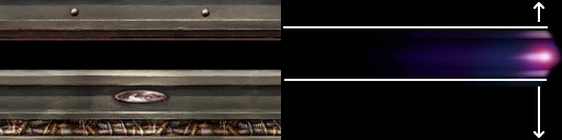
The reason the texture was scaled horizontally by such a large value is to "lengthen" the pulse effect so it seems to to cover the entire width of the wall borders on which this shader is used as can be seen when looking at the wall borders while in q3dm6. Here's what part of the texture approximately looks like once stretched to the above scale:

Please note that since the texture, once stretched is (28.57 x 256 pixels), thus about 7314 pixels wide (!!), it's impossible for me to show the entire texture tile. So the picture above (650 pixels wide) is less than 1 tenth of it's entire width.
Now although the tcmod scale parameter is essential to make the pulse look good on the shader, this isn't what makes it scroll across the border texture's "slot" as such. The heart of the "scrolling mechanism" is of course the keyword:
tcmod scroll -0.65 0
This is what makes the border11c_pulse1b.jpg texture scroll horizontally across the brush face or patch on which this shader is applied. The values used are in number of texture tiles per second. But, keep in mind that since the textured was scaled previously with the tcMod scale command, the actual texture tile size is now 7314 x 128 pixels and not 256 x 128 pixels anymore! It's very important to keep this in mind when setting the scroll speed values of the texture. This is one of the reasons why the tcMod scroll keyword should always be the very last tcMod type keyword used in a shader stage. So here, the final scrolling speed of the border11c_pulse1b.jpg texture will be:
7314 x 0.65 = approx. 4754 pixels per second
Which turns out to be very fast. The sign in front of the scroll value changes the direction in which the texture will scroll: here a negative value makes the texture scroll towards the right.
This concludes my dissection of this shader. Keep in mind that what is described here is the step-by-step way to analyze a shader. By extracting the images and referring to the shader manual, you can use this method whenever you need to figure out how a shader works.