Tutorial written by Eutectic. Mirrored here for archival purposes. Note his example file/textures have been lost to time, however all of the images for this tutorial were preserved.
Advanced Arches
by Eutectic
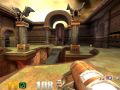
While I was exploring Id's Quake III Arena maps, studying the architectural and style elements to "exercise my eye" for future maps, this decorative arch in the main courtyard of House Of Pain (q3dm2) caught my eye. Take a look at the screenshot in Fig. 1 below:
Figure 1 - Decorative arch in House Of Pain.I think this is a beautiful architectural element. Notice how round and smooth the edges of the arch look? When I first saw it, I knew I just had to make arches like this one.
Arches like these can be extremely hard or very time consuming to make without using certain techniques. In this tutorial, I'll show you the methods I used to make an arch like this one. I'll also give you some insight on the mistakes I made along the way so you'll understand some things I discovered with this type of patch manipulation.
This is an advanced tutorial, so I'll assume you know the basics of Q3Radiant, such as drawing and clipping brushes, creating patches, texturing, etc. If you don't, please refer to Ricebug's basic QeRadiant and Q3Radiant tutorials before you attempt this one. If you're unfamiliar using patch bend mode, please refer to Tatoo's excellent tutorial at Rust.
Determining Textures and Dimensions
When reproducing this type of architectural element, your main guide in determining the sizes and shapes of brushes/patches must always be the textures (or rather shaders in Q3A), which ones were used, and how they line up in relation to one another.
First, we have to find which shaders were used in the making of the arch. The console command shaderlist can help you determine this. But in order for this list to be useful, we have to save it in a logfile, which can be opened with a text editor while we're working in Q3Radiant. Run the map in Q3A and type the following commands:
/clear
/shaderlist
/condump q3dm2_shaderlist.txt
This will automatically create a text file named q3dm2_shaderlist.txt and dump the output from the shaderlist console command into it. To save ourselves some time, here is the list of shaders that were used for this arch:
- gothic_wall/dm5_archifin: main arch face brush.
- gothic_trim/supportborder: column faces.
- gothic_trim/supportborderside: column sides (stretched to 0.4 horizontal and vertical scale).
- gothic_door/archpart1: column trim block's faces.
- gothic_door/archpart2: column trim block's sides.
- gothic_trim/pitted_rust3: column trim block's tops and bottoms.
- gothic_trim/pitted_rust3: arch patches.
Let's take a closer look at the arch and give ourselves some visual reference cues we can use to make sure the arch will be as close as possible to the original one in q3dm2. I have highlighted those in Fig. 2 below:
Figure 2 - Dimensions of the arch in House Of Pain.
Looking at Figure 2, notice how:
- The top center "pique" detail and the brownish thingies of the arch face texture meet the inner edges of the arched patches. This will be crucial when aligning those later.
- The left hand side "wing" detail of the arch face is nearly flush with the arch patch's inner edge. This means right from the start that we'll make that side of the arch before the other one.
- The top of the left hand side of the column trim block is at the same height as the "hand" of the engraved statue in the arch face texture.
- The top of the right hand side of the column trim block is at the same height as the middle of that "oval hole" of the engraved snake statue in the arch face.
At this point, we have enough cues to build the face and columns of the arch. I could let you figure this out but again, to save ourselves some time, here are the dimensions (seen from the front view):
- Main arch face brush: 176 wide x 48 deep X 384 high.
- Main column brushes: 32 wide x 80 deep X 208 high and spaced 128 apart.
- Column trim blocks brushes: 40 wide x 88 deep X 32 high and centered on top of the columns.
Once your brushes are drawn, hit 4 to set the grid to 8 units, hit X for brush clipping mode and clip the tall arch face brush to the shape shown in Fig. 3 below:
Figure 3 - Arch face brush after clippping.
In Q3Radiant, clipping a brush will reset the texture alignment to the default values, so it's best to clip the brush first and align the texture later. If you centered the brush on the XYZ (0 0 0) origin like in the example above, a horizontal shift value of 96 and a vertical shift of 0 (default) will give you the proper alignment for that texture.
Then set the 3 top faces of that brush to the common/caulk shader as seen in Fig. 4 below:
Figure 3 - Set the caulk shader on the top 3 faces of brush.
The caulk shader is normally used for brush faces that share a common plane with an curved patch to avoid Z-buffer conflicts. Although this won't be the case here, I set caulk on those faces because they will end up inside the curved arch patches and won't be seen by the player. But since patches do not block VIS, those faces WOULD be seen by the engine. Using caulk is not essential here but it will prevent the engine from unnecessarily rendering those 3 faces.
Align the textures on all the other brushes. Don't forget that the gothic_trim/supportborderside texture must be stretched to 0.4 horizontal + vertical scale to fit the sides of the column brush properly. If you centered the brush on the XYZ (0 0 0) origin like in the example above, a horizontal shift value of 16 and a vertical shift of 0 (default) will give you the proper alignment for that texture.
Making the Curved Arches with Thickened Patches
Now here comes the hard part, where I told you I made many mistakes (took me 2 days to get this right). I started off making a square cylinder, trying to bend it at the bottom and top ends into the proper shape, and failing miserably after numerous attempts. The central problem was that I could not obtain the proper shape and have the upper end of the cylinder's vertices fall in the right spot + angle while remaining perfectly aligned to the grid.
The wrong way to go about it is thinking you can just "whip" the cylinders into submission by adding extra rows and using patch bend mode. I started out with a rectangular brush the same width + depth as the columns and 160 tall. Next, I turned it into a square cylinder, doubled the number of rows (CTRL + Keypad plus) twice and redistributed those rows evenly across the cylinder (CTRL + E) as can be seen in Fig. 5. Then I switched to bend mode and ate my heart out as can be seen in Fig. 6 to 8 below. Remember, this is the WRONG way!
Figure 5 - Making the square cylinder: all those extra rows should do the trick right?
Figure 6 - Let's start bending. This looks about right...
Figure 7 - Hey! This is starting to look good...
Figure 8 - DOH!! Can't make it fit!
And this is just one example. I tried starting off with a shorter/taller cylinder, tried increasing/decreasing the patch rows, using a smaller grid setting, etc... to no avail. I simply could not get the exact shape I needed. Then I thought: "Maybe bending a square cylinder is not the proper method?... What if I started out by shaping a flat patch for the front cap and thickened it afterwards?...". What the heck, don't have anything to lose at this point right?
The right way: Draw a rectangular brush the same width and depth as one of the columns and any height you want (doesn't matter) and make it into a simple patch mesh using the default 3 x 3 setting. Then, with vertex manipulation mode on (V key), move the top end's 3 vertices to their final location and moved the 3 middle vertices up by 4 units as can be seen in Fig. 9 and 10 below:
Figure 9 - Making a simple patch mesh
Figure 10 - Moving the vertices to their location
Now switch to the YZ side view and move the flat patch 16 units in front of the arch face brush to see how much extra vertex manipulation would be required to give it the outline needed. Since this patch will become one of the arch caps, this puts it in the right place before thickening, as seen in Fig. 11 and 12 below:
Figure 11 - Moving the patch to its location
Figure 12 - The patch fits nicely at first try
Your patch should now fit nicely. With the patch still selected, click on the Curve menu and selected Thicken. In the dialog that appears as shown in Fig. 13, set the thickness to 80 (which is how deep the arch must be). Leave the seams option checked because this will automatically create the inner and outer sides of the arch. The result can be seen in Fig. 14 below:
Figure 13 - Setting patch thickness dialog to 80
Figure 14 - Thickened patch completed
The term, thickening is just an expression that may confuse some mappers. By definition, a patch is a 2-dimensional surface and therefore cannot really be thickened. What thickening does is automatically create 5 new patches based on the one that was selected, resulting in a box made from 6 individual patches.
One last detail before copying our newly-created "half-arch" is to delete the top and bottom "caps" created by Thicken patch. They won't be visible in the game, so there's no reason to keep them. The top cap is easy to select but the bottom one is over the column trim block. We'll employ one of Q3Radiant's powerful features. With the column trim block selected, click on the View menu and chose Hide Selected. See Fig. 15 and 16 below:
Figure 15 - Column trim block selected
Figure 16 - "Hide selected" feature
With the trim block "out of the way" you can now select the 2 cap patches to delete them as seen in Fig. 17 and 18 below:
Figure 17 - Selecting the lower cap
Figure 18 - Selecting the upper cap
Finally, select the four remaining patches that make up the half-arch, copy them, move them into place, and rotate by 90 degrees in the Z axis by clicking twice on the RotateZ button: ![]()
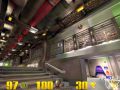
Here's what the arch looks like in the game after compiling:
Figure 20 - The thickened patch arch in the game.
But wait!... something's not quite right. It looks OK but how come those edges stand out so much when the original arch in q3dm1 looked so rounded and smooth? (Compare this screenshot with Fig. 1 at the beginning of this tutorial to see what I'm talking about here.)
Here's why: My arch halves are made from four separate patches (four separate and individually textured surfaces). A square cylinder, however, is only one surface with one texture that wraps around like a skin does on a model. Therefore, the arch in q3dm1 looks smoother because each half-arch is made from a square cylinder after all.
So now we're back to Square One and all the original problems. If you find the arch we just made good enough for your own purposes, then you can use the method described above. However, if you're like me, and you want your arches to have that extra refinement, read on. I took the time to include this in my tutorial and held you up for 2 main reasons:
- The above arch, although not perfect, isn't bad, and is relatively quick and easy to make. Plus, we can now use the initial simple patch mesh as a template to shape the cylinder.
- In some cases, you might prefer a "squarish" look over a "rounded-off" look. A curved ventilation duct in a base style map could be an example.
Ironically however, making the above arch with a square cylinder and using the proper shaping techniques is just as easy as the thickened patch method and actually involves less steps! So let's move along and do it the right way this time.
Making the Curved Arches with Square Cylinders
First, delete all the patches made in the previous section except for the initial right hand side face cap. Then, make sure you have the gothic_trim/pitted_rust3 shader selected in the shader selection window and draw a brush 32 wide x 80 deep and any height you want.
Figure 21 - Drawing the square cylinderGo to the Curve menu and select Square Cylinder. Take a look at Fig. 21 on the left and note that I placed the cylinder close to our previous patch mesh. The reason is because we'll be using it as a template to place the vertices of our cylinder in the next step.
Here, I made the brush 192 units tall before turning it into a cylinder. Again, I want to emphasize that the initial height has no importance because we'll only be moving the vertices to shape the cylinder. If we wanted to bend the cylinder however, the initial height might matter in some cases.Deselect the square cylinder and select the flat patch right next to it on the left. Hit V to switch to vertex manipulation mode. Take a look at Fig. 22 on the right and note where the vertices are located.
Toggle off vertex manipulation mode by hitting V again and deselect the patch.
Figure 22 - Noting the location of the vertices
Figure 23 - Shaping the square cylinderSelect the square cylinder and hit V to switch to vertex manipulation mode. Click and drag all the cylinder's vertices until they are located in exactly the same place as the patch mesh's vertices. (You can alternately select and deselect the cylinder patch if you get confused as to the vertices exact locations.)
If you look at Fig. 23 on the left, you will notice that once the vertices are all moved, our square cylinder's rows and columns match the patch mesh's rows and columns perfectly.
From here on, the rest is a piece of cake. Just delete the simple patch mesh, reselect the square cylinder, hit the spacebar to copy it, rotate the copy you just made by 180 degrees in the Z axis by clicking twice on the RotateZ button: ![]() . Move the cylinder to its location and you're done. Save, compile your map and launch it in the game.
. Move the cylinder to its location and you're done. Save, compile your map and launch it in the game.
Figure 24 - The square cylinder arch in the game.
Ahhh! Now that's more like it. This is the smooth, rounded off effect look I was looking for. Compare Fig. 24 above with Fig. 20 farther up in this tutorial.
Smoothing Those Square Cylinders
In the above example, we were able to obtain exactly the shape we were looking for with a patch with the default number of rows and columns. But what if, for example, you wanted to make an arch which is the same width but much taller? You might find yourself in a situation where a patch with only 6 rows would make your arch sides look a bit rough and squarish.
Well, there's a neat trick I found that I want to share with you. In fact, the whole exercise of this tutorial would have been sort of futile without this. Of course, most of you already know that you can increase the number of rows and columns in a patch and redistribute those evenly along the patch's surface. But most of the time, we do this before shaping the patch. Well there's a way you can use this feature advantageously after you have shaped your patch.
Let's pick up on our previous example at the stage when we had just finished shaping our first cylinder and before we deleted the simple patch mesh. Since I made you delete your simple patch mesh, you'll have to redraw and reshape it (you can use your right hand side cylinder as a template for this). Delete the left hand side cylinder (when seen from the front view) and select the remaining cylinder.
Go to the Curves menu and select Add (2) Rows as shown in Fig. 25 below or simply hit CTRL + Keypad Plus.
Figure 25 - The curve menu's adding rows dialog
Please note that this will effectively double the number of rows in the square cylinder and will concentrate the new rows at the top of the patch. In this particular case, you could have just as well selected Insert (2) Rows instead, the only difference is that the extra rows would have been added at the bottom of the patch instead.
Please note that the following Q3Radiant Curve menu selections: "Insert (2) Columns", "Add (2) Columns", "Insert (2) Rows" and "Add (2) Rows" do NOT add 2 columns or 2 rows, the number 2 means DOUBLE the amount of columns or rows in the currently selected patch. The same way, the Q3Radiant Curve menu selections: Delete + "First (2) Columns", "Last (2) Columns", "First (2) Rows" and "Last (2) Rows" do NOT remove 2 columns or 2 rows, they DIVIDE BY 2 the amount of columns or rows in the currently selected patch.
Figure 26 - Doubling the rows of the cylinderOh no!! I just FUBAR'ed my perfectly good cylinder!... Don't worry, everything's under control. Trust me.
Note how the extra rows were inserted in the top half of the cylinder, while the bottom half's density remains relatively unchanged. This is what we'll fix. Go to the Curves menu again and select Re-disperse + Rows as shown in Fig. 27 on the right or simply hit CTRL + E
This will evenly re-disperse the newly inserted extra rows along the cylinder's height.
Figure 27 - The curve menu's redisperse rows dialog
Figure 28 - Redispersing the rows of the cylinderOh no!! I made you FUBAR the cylinder even more! This may look like a disaster in the making, but we're actually going somewhere here. Just keep reading...Toggle vertex manipulation mode by hitting V, switch to a two-unit grid and zoom in close on the cylinder.
As Fig. 29 shows on the right, the three sets of vertices of the cylinder's center portion are all perfectly lined up on a two-unit grid. This will make it painless to reshape that cylinder to a shape both aligned to the patch mesh template and much smoother.
Figure 29 - The vertices are lined up on the grid
Now we're going to reshape our cylinder. Start with the middle three vertices, since those are the easiest to align. Using the simple patch mesh as a template, drag the vertices until they match with the patch's edge and center row points. The result is shown in Fig. 30 below.
Figure 30 - Dragging the middle vertices into place.
Now drag the lower three vertices to a place about halfway inside the second row of the simple patch mesh. At that point, it's a matter of tweaking each until the rows and columns of the cylinder match the patch mesh as closely as possible. Keep in mind that it's neither possible or necessary to align both perfectly. Refer to Fig. 31 below for the final position of the vertices.
Figure 31 - Dragging the lower vertices into place.
Lastly, drag the upper three vertices to a spot somewhere inside the next-to-last row of the simple patch mesh. Here again, it's a matter of tweaking each until you get the best possible match between the cylinder and the patch mesh. The final position of the vertices can be seen in Fig. 32 below.
Figure 32 - Dragging the upper vertices into place.
...and we're done. At this point, you can delete the patch mesh, copy your cylinder, rotate it and move it in place. Save and compile your map, then load it in the game. You will notice that there's not much difference visually between those denser cylinders and the previous ones.
That's because in the case of this particular arch, the spread (height- and width-wise) of the cylinder patch is small in comparison to the number of rows and columns. Thus, you're better off sticking with the first cylinder with the default number of rows, since doubling those will only give the engine more polygons to render without any real gain in visual quality. So why did I make you do this?
Well, not all arches are alike, and in cases where you want to make an arch the same width as this one but much taller, increasing the number of rows will probably be necessary to make it follow a specific contour you have in mind and to maintain a smooth appearance. By learning the technique in depth right away, you will be better prepared later when you want to make newer shapes of ever increasing complexity. Keep in mind though, that what I put forth here is only a tiny fraction of all the things you can do with patches.