This tutorial is relevent to modelers, modders and people who would like to test out the Aero Empire game engine. See bottom for links and screenshots.
Starting the Program
When you double click the program, it will bring up a form which allows you to browse for a scene file, turn shadows on and off, and set the window size (resolution boxes). Additionally, if you check full screen, it will set the screen resolution to the set resolution and start the program in fullscreen mode (make sure the resolution is a valid display mode, or it will say that fullscreen mode is not supported).
The program also starts a console window, which will report any warnings or errors during execution. If the program closes, then an error will be sent to the command line which can be used for debugging purposes.
Controls
You can left click and drag the mouse to rotate around the view location (initially (0, 0)). You can right click and drag the mouse to zoom in and out. The arrow keys allow you to move the camera (and view location) left, right, up and down with respect to the current viewing direction. If you hold shift and use the arrow keys, it will move the light source. Holding down control while moving the camera position or light source, it will increase the movement speed, and holding down alt+control will move the moon (if loaded). Finally, the escape key exits the program.
Scene Files
Scene files are files which define a scene using a simple interpreted pseudo-language. Everything is case-sensitive, and all defined names must be one word (although filenames may be multiple words for paths containing spaces).
Below are the objects and structures used in scene files:
------------------------------
Creating an Image:
------------------------------
Image image_name
LoadPng file.png
LoadRaw file.raw
Type width height channels
End
This will create an image by name image_name, which will be a reference to this image for use in other commands. LoadPng will load a png file (RGBA channels), and is recommended. LoadRaw will load a raw file with specified height, width and number of channels (using Type keyword). Raw images are loaded left to right, bottom to top (opengl) order. However, most images are saved left to right, top to bottom. To fix this, just flip the image vertically before saving. LoadRaw is considerably faster than LoadPng, however LoadPng is much easier to work with.
------------------------------
Creating an Object:
------------------------------
Object object_name
Model process file.obj
Heightmap image_name x y z width height depth
Cloud seed x y z width height depth
Texture image_name
NormalMap image_name
MiscMap image_name
Material diffuse phong cells two_sided
CustomColor r g b
End
Like above, this will create an Object with object_name being a reference to it. You must call Model, Heightmap or Cloud - Model will load an obj1 from a file, and Heightmap will create a heightmap from the specified image, and Cloud will generate a random cloud (ellipsoid with noise) with seed being a random number, x, y, z being the bottom left corner of the heightmap, and width, height depth being the size in the three dimensions. Texture sets the texture of this object to an image, NormalMap sets the normal map of this object to an image, and MiscMap sets the misc map of this object to an image. Material sets the material of the object - diffuse sets how bright the object is (0 is black, 1 is white), phong sets how bright the highlights are (0 for no highlights, 1 for highlights), cells sets the strength of the cell shader (1 being normal diffuse shading, and higher values produce sharper boundaries between dark and light regions), and two_sided sets how much light can pass through the object (0 means no light passes through, 1 means all light passes through). CustomColor sets the custom color (if defined by the misc map) red, green and blue values.
------------------------------
Creating an Composite Object:
------------------------------
Composite composite_name
...
End
Any AddObject, AddDynamic or AddObjects functions (see below) between the composite line and the end line will add the objects to a composite object instead of the scene that you can transform as if it was one unit, and add it multiple times.
1 Obj files loaded must be triangulated and contain normal and tex coords. The program will skip facets which are not triangulated or do not contain normal and tex coords, displaying a warning. The process parameter can be 0 or 1, if it is 1, then the model is processed (fixing simple normal problems), and ridge/crease lines are added.
Below is a list of functions:
- AddObject object_name - adds an object directly to the scene.
- AddDynamic object_name
Pos x y z
Rot pan tilt roll
Scale x y z
AnimRot pan tilt roll
Texture image_name
NormalMap image_name
MiscMap image_name
Material diffuse phong cells two_sided
CustomColor r g b
EndAdds a Dynamic Object to the scene. This object can be translated, scaled or rotated, and there is a simple animation function (AnimRot) which rotates the object by the specified amount every frame. Note that all angles are in degrees. You may also change the texture, normal map, misc map, material and custom color of the dynamic object.
- AddObjects object_name file.trans - loads an object with many different translations as specified by the .trans file2. This is useful for instancing many objects.
- AddComposite composite_name
Pos x y z
Rot pan tilt roll
Scale x y z
AnimRot pan tilt roll
EndExact same functionality as AddDynamic (above), but this is for adding a composite object. The transformation parameters need not be specified - but you must include the 'End'.
- AddLight (x y z) (r g b)
Adds a point light at position (x, y, z) with color/magnitude (r, g, b )
- AddVolume object_name density
Adds an object to the scene as a volume (cloud) with specified density. The object must be a closed mesh.
- AddClouds seed x y z width height depth density
Utility function which generates and adds several clouds to the scene in a 3 layer stratified style. All clouds generated with passed seed and density, and within specified bounds.
- Mountain composite_name seed x y z width height depth
Randomly generates a mountain with given seed, and within the specified bounds, and stores it as a composite object of the specified name (which can be added using AddComposite). - SetSun theta phi
Sets the sun's position in the sky.
theta - sets the sun's horizontal angle 0-360
phi - sets the sun's vertical angle, 0 is up, 90 is horizontal, 180 is down - SetMoonColor r g b
Sets the moon light color to the specified r g b values (moon must be added to take effect).
- SetMoonSize size
Sets the size of the moon. 4 is about a typical earth-sized moon. The larger the moon, the more light it adds.
- SetMoon texture_image normal_image
Sets the moon texture and normal (image objects).
- Skybox east west north south top bottom
Sets the skybox (night sky) to display. Requires 6 image objects - the east, west, north, south, top and bottom side of the skybox.
- Window width height
Sets the width and height of the window. Overrides the value specified in the model viewer form.
- Lines enable
Whether to enable lines or not. If enable is 1, then lines will be added, if 0, no lines will be added. - Shadows enable shadow_maps shadow_samples
Sets shadow settings. If enable is 1, then shadows will be added with the specified number of shadow maps and shadow samples (must be > 0, higher numbers increase quality). Otherwise, no shadows will be added.
- VolumetricShading enable volumetric_samples
Sets volumetric shading settings. If enable is 1, then volumetric shadows and godrays will be added with the specified number of samples (must be > 0, higher numbers increase quality). Otherwise, no volumetric shading will be added.
Additionally, there is one constant: UnitCube - a predefined object which is a cube from (-1, -1, -1) to (1, 1, 1). You can add it using AddObject UnitCube.
2 Trans files are plain text files with one of the following per line:
t x y z
r pan tilt roll
s x y z
r rotates all following objects by the specified values (degrees) until the next r command (before any r command, this is 0 0 0).
s scales all following objects by the specified values until the next s command (before any s command, this is 1 1 1).
t adds an instance of the object with specified scale and rotation at the specified x, y, z coordinates.
Of course, the easiest way to get used to scene files is to see an example one. Here is the scene file used to display the marketplace:
Marketplace.scn wrote:
#Set sun positionSetSun 150 75#---------------------#Load ImagesImage marketplace_texLoadRaw Marketplace/marketplace.rawType 512 512 4EndImage marketplace_miscLoadRaw Marketplace/miscmap.rawType 512 512 3EndImage moonLoadRaw moon.rawType 128 128 4EndImage moon-normalLoadRaw moon-normal.rawType 128 128 3EndImage sky-eastLoadRaw stars-east.rawType 512 512 3EndImage sky-westLoadRaw stars-west.rawType 512 512 3EndImage sky-northLoadRaw stars-north.rawType 512 512 3EndImage sky-southLoadRaw stars-south.rawType 512 512 3EndImage sky-topLoadRaw stars-top.rawType 512 512 3EndImage sky-botLoadRaw stars-bot.rawType 512 512 3End#---------------------#Set Moon and SkyboxSetMoon moon moon-normalSetMoonColor 1 1 1SetMoonSize 4Skybox sky-east sky-west sky-north sky-south sky-top sky-bot#---------------------#Load ObjectsObject marketplaceModel 1 Marketplace/marketplace.objTexture marketplace_texMiscMap marketplace_miscMaterial 1 0 5 0CustomColor 1 1 1End#---------------------#Add objects to sceneAddDynamic marketplaceRot 0 0 90End#---------------------#Add lights to sceneAddLight (11 7 3.2) (2 .6 .172)AddLight (21 7 3.2) (2 .6 .172)AddLight (-11 7 3.2) (2 .6 .172)AddLight (-21 7 3.2) (2 .6 .172)AddLight (11 21.2 3.2) (2 .6 .172)AddLight (21 21.2 3.2) (2 .6 .172)AddLight (-11 21.2 3.2) (2 .6 .172)AddLight (-21 21.2 3.2) (2 .6 .172)
This produces the same scene used to showcase the marketplace, which you can see screenshots of here: Moddb.com


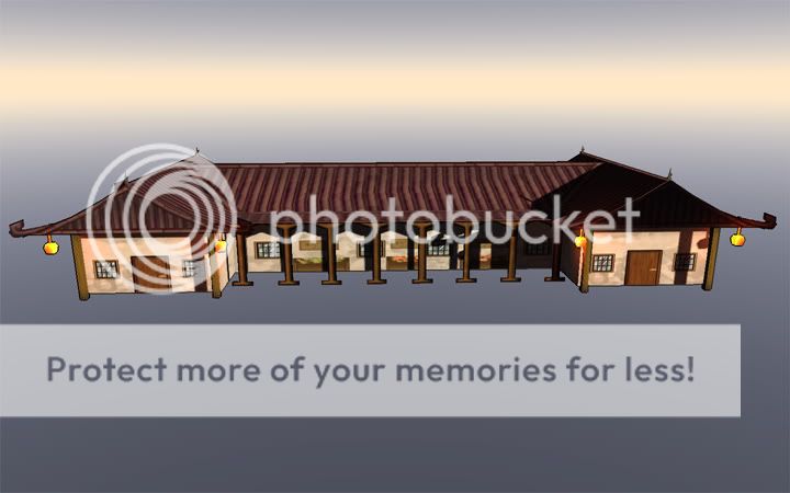
The third image changes the custom color of the marketplace using the CustomColor command.
You can download the ModelViewer here: Moddb.com
It is my hope that this tutorial and tool will help potential modelers and modders experiment with the engine. Let me know what other features you think would be useful, and I will update this article with any new functions and objects added. Look forward to more tools and tutorials as the game comes closer to completion.
If you have questions, feel free to contact me.
- David.
This looks interesting. So this is a tool for a custom built engine?
I don't know what I could use it for, but it looks neat.
Yes - this tool is for Aero Empire's engine, the Cumulonimbus Engine, which was custom built for Aero Empire (although could be used for other games in the future).
This tool is useful simply for rendering scenes in the Cumulonimbus Engine - although there may be more uses added to it as more functionality is needed and developed.
HELLO DAVE
Www2.corpseclothing.com