Where is Poppy
Your First Custom Entity
You can find the accompanying PDF here.
The Original Tutorial can be read here.
You can Download the Project Source Code and Releases through Github.
In this tutorial I take you through the steps required for creating your own custom mesh loading entity. This is the second part in a series of tutorials covering the creation of the project “Where is Poppy”.
You can check out the First tutorial here.
What you will need
- Text Editor (Notepad++, Notepad, Sublime etc.)
- Visual Studio ( 2010 – 2015*)
- Half-Life SDK from GitHub (*Use this Fork from Malortie for VS2015)
- Steam and a copy of Half-Life
- Hammer (Worldcraft), Jackhammer (Or a GoldSrc Level Editor of Choice)
- Perforce Server & Client (or any Version control system)
Overview
Basically what we want to achieve is the loading of a mesh/model (.mdl) into our Mod. As it’s a static mesh we do not have to worry about movement code and simply need to ensure its placed correctly and that it has a physical presence (collision volume) preventing the player from walking through it.
We will also load animations since meshes can still remain in one location and also animate. For instance, vegetation doesn’t move around due to its roots but it can sway in the wind so we want to provide an option for this possibility.
We will also load animations since meshes can still remain in one location and also animate. For instance, vegetation doesn’t move around due to its roots but it can sway in the wind so we want to provide an option for this possibility.
Preparation for Coding
Note: I’ve noticed that when I run Half-Life in debug mode from Visual studio and it triggers either a breakpoint or bombs out due to an error, my computer enters a state where it cannot return, and thus I need to reboot. To avoid this, I simply run the game in windowed mode.
My debugging options in hldll properties now look like this:
Visual Studio:
Be sure to set it again for all configurations and set the program you will be debugging through to hl.exe in your Half-Life directory. Then set the command to:
Jackhammer Run Map:
My debugging options in hldll properties now look like this:
Visual Studio:
Be sure to set it again for all configurations and set the program you will be debugging through to hl.exe in your Half-Life directory. Then set the command to:
-game WhereIsPoppy_dev -console -dev -condebug -window -h 720 -w 1280 +map test_01
Jackhammer Run Map:
-game WhereIsPoppy_dev -console -dev –condebug -window -h 720 -w 1280
Header and CPP Files
In the solution explorer under hldll > Header Files > dlls lets create a custom header file to include all our newly created Classes and Functions related to point entities.
For now, that will only cover a static model that doesn’t move (but can animate on the spot).
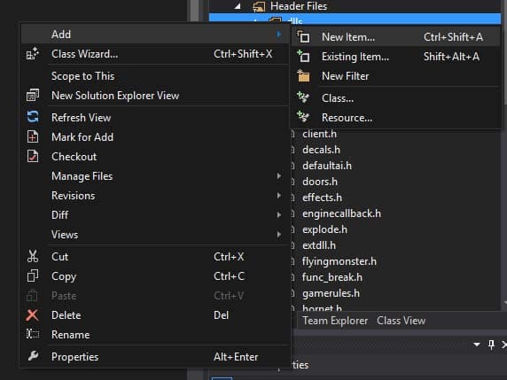
Right-Click on dlls and select Add -> New Item.
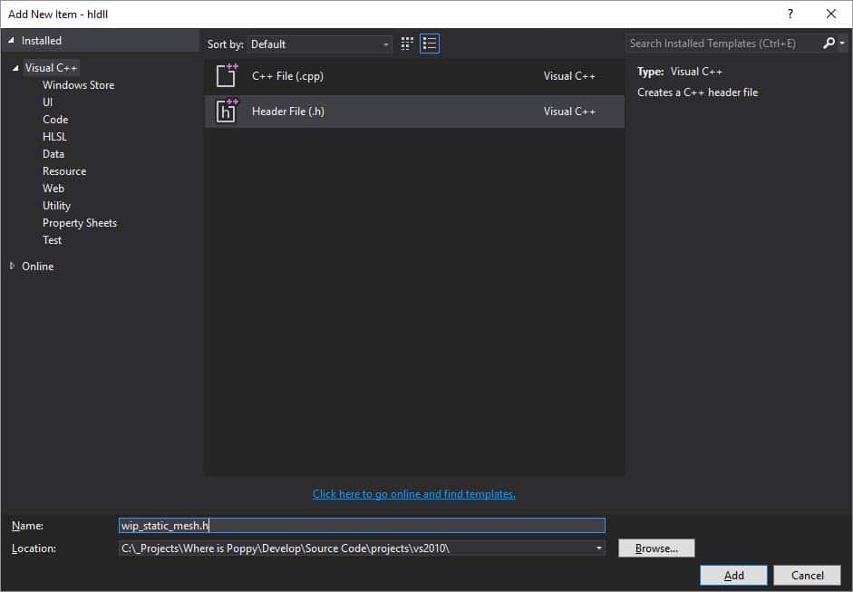
Select Header file and give your file a unique name, I call this file “wip_static_mesh.h” Now let’s add a .cpp file under hldll > Source Files > dlls.
Right-Click on dlls and Select Add -> New Item, this time select C++ File (.cpp) and name it the same way you called your header file with the exception of the extension which should be .cpp “wip_static_mesh.cpp”
Next let’s start preparing what will be the very minimum you will need to get a Static Mesh loading in your Mod.
I typically always start with a block comment at the top which looks something like this.
I then define the Header file and include any dependencies the class will require.
Next we will create the Class itself and give it a unique name from anything else that has been created in the project so as to avoid conflicts in naming and reference etc.
The class will be called CStaticMesh and it inherits from CBaseAnimating so that we can use some cool functions from it later
We declare our functions which will be used in the cpp file later.
Spawn: which pretty much spawns our entity in the world when called upon either by other code or a level including it.
Again starting with a comment block just to keep things orderly.
Next we include a reference to our header file we created earlier. Since we include all other references in the header file there is no need to #include anything else here.
Then we must link our class CStaticMesh to what hammer will recognise it as: “wip_StaticMesh” (this is what we will add to our custom FGD shortly
Next up is the Spawn function which will take control of adding our mesh to the world.
If we don’t Precache the model the game will hang on start-up so it’s a necessary, step. If you remove the model file or rename it Half-Life will exit on load complaining that its can’t find the model. You can read a little more about precaching here.
Next we set the model itself using the SET_MODEL Macro/function
That’s all we need on the programming side to get a static mesh loaded into the Game.
Save your Header and CPP file and compile. You should see that everything compiled correctly and a file was copied to your mod directory (if you are following on exactly from my previous tutorial)
Let’s create in your text editor of choice a new file called after your mod. In my case I will call it wip.fgd and I will save it to my “WhereIsPoppy_dev” Mod Directory inside the Half-Life Directory.
This is what my wip.fgd file looks like.
Basically an FGD is a descriptor for Hammer to interface with classes you have created in code. This represents your CStaticMesh Class inside Hammer. In the entity list when we add this FGD to our mod we will see a new entry called “wip_StaticMesh” which reads this Key : Value Data to figure out what options to give the user within hammer.
In this case we will only see a browse dialog for a Model File. We set some other settings such as color and size which correspond to the color and size of the initially placed entity prior to selecting a Model. More on this later.
Save your FGD and let’s fire up JackHammer.
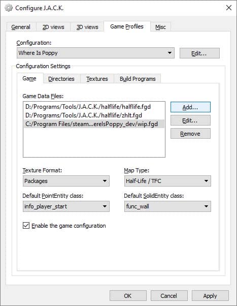
In JackHammer (or any good hammer editor/variant) lets add our custom FGD file under Tools > Options > Select “Game Profiles” > Add..
Open the Map we started working on from the previous tutorial “Test_01.map”. It should be available in Jackhammers, recent file list.
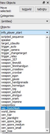
Select the Point Entity Tool

Then on the Right hand side of the editor under the Objects pane select wip_StaticMesh
Click anywhere on the ground to add our custom entity. Observe a green box protruding from the floor where you clicked.
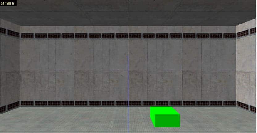
Its green because in our FGD we set the color to (0 255 0) The size of this box should also be what you had set in the FGD.
Select the Selection Tool.

Either Right Click on the instance of the “wip_StaticMesh” entity, double click on it, or click on it and hit ALT + ENTER to bring up the properties page for your selection.
You should see something along these lines:
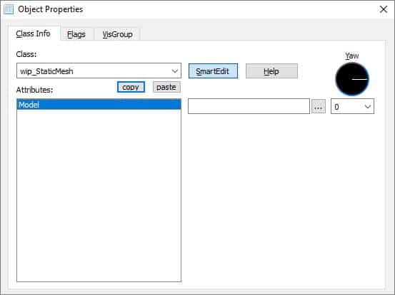
Let’s select a model for our entity. Since we have no models added to our mod yet we can grab one from Half-Life’s Valve/Model folder.
I select “tree.mdl” which is the Xen Tree from Half-Life
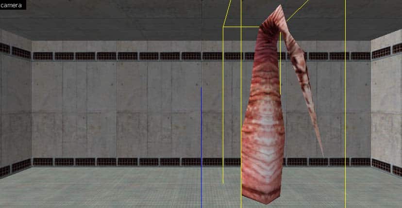
You should see the model update in jackhammer.
Note: There is no WYSIWYG Editor for GoldSrc or Source Games simply because the levels still need to be compiled and are only then loaded by the Engine. Recent Game Engine adaptations such as UE4, CryEngine & Unity use an instance of the Engine as the Level Editor so you have a clear idea of that the end result will be.
For example, if you loaded tree.mdl like I did you will notice that it is currently animated in the Editor but I know that it won’t animate in the game because I haven’t added code to my entity to handle that yet.
I will now play with the Yaw setting in the properties and set it to 180 so that the entity will face me.
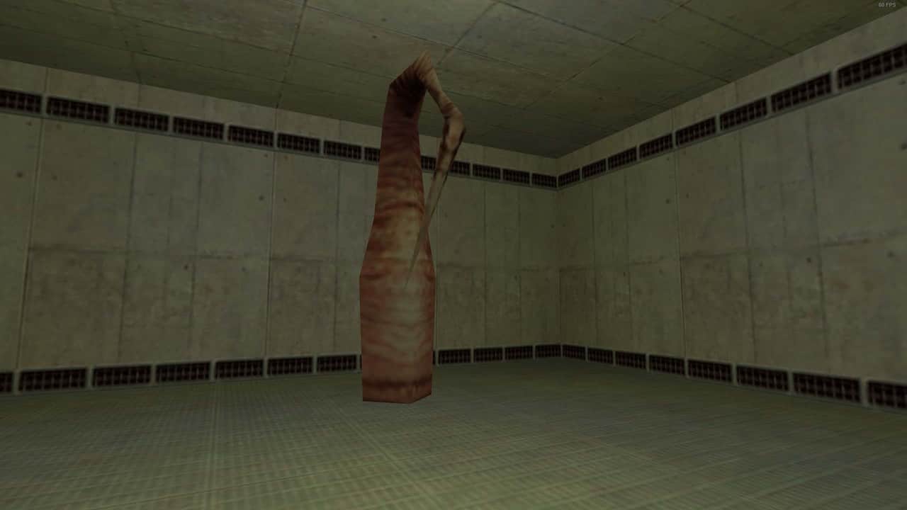
The next step is to Compile the Map and Run it. This assumes that you have compiled your code to include your new entity.
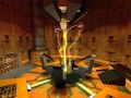
If all went well you should see your custom entity loaded in the game.
For now, that will only cover a static model that doesn’t move (but can animate on the spot).
Right-Click on dlls and select Add -> New Item.
Select Header file and give your file a unique name, I call this file “wip_static_mesh.h” Now let’s add a .cpp file under hldll > Source Files > dlls.
Right-Click on dlls and Select Add -> New Item, this time select C++ File (.cpp) and name it the same way you called your header file with the exception of the extension which should be .cpp “wip_static_mesh.cpp”
Next let’s start preparing what will be the very minimum you will need to get a Static Mesh loading in your Mod.
Header
/******************************
Where is Poppy
February, 2017

wip_static_mesh.h

Static Mesh Loader for the mod
Where is Poppy

*******************************/
I then define the Header file and include any dependencies the class will require.
#ifndef WIP_STATIC_MESH_H
#define WIP_STATIC_MESH_H

#include "extdll.h"  // Required for KeyValueData & Export Parts
#include "util.h"  // Required Consts & Macros
#include "cbase.h"  // Required for inheriting from CBaseAnimating
Next we will create the Class itself and give it a unique name from anything else that has been created in the project so as to avoid conflicts in naming and reference etc.
The class will be called CStaticMesh and it inherits from CBaseAnimating so that we can use some cool functions from it later
class CStaticMesh : public CBaseAnimating
{
private:
 void Spawn(void);
};

#endif
We declare our functions which will be used in the cpp file later.
Spawn: which pretty much spawns our entity in the world when called upon either by other code or a level including it.
Source CPP File
/******************************
Where is Poppy
February, 2017

wip_custom_point_entities.cpp

contains the source functions
related to custom point entities
for Where is Poppy

*******************************/
Next we include a reference to our header file we created earlier. Since we include all other references in the header file there is no need to #include anything else here.
#include "wip_static_mesh.h"
Then we must link our class CStaticMesh to what hammer will recognise it as: “wip_StaticMesh” (this is what we will add to our custom FGD shortly
LINK_ENTITY_TO_CLASS(wip_StaticMesh, CStaticMesh);
Next up is the Spawn function which will take control of adding our mesh to the world.
If we don’t Precache the model the game will hang on start-up so it’s a necessary, step. If you remove the model file or rename it Half-Life will exit on load complaining that its can’t find the model. You can read a little more about precaching here.
Next we set the model itself using the SET_MODEL Macro/function
void CStaticMesh::Spawn(void)
{
 PRECACHE_MODEL((char *)STRING(pev->model));
 SET_MODEL(ENT(pev), STRING(pev->model));
}
That’s all we need on the programming side to get a static mesh loaded into the Game.
Save your Header and CPP file and compile. You should see that everything compiled correctly and a file was copied to your mod directory (if you are following on exactly from my previous tutorial)
Forge Game Data (.fgd)
This is what my wip.fgd file looks like.
// Where is Poppy Forge Game Data
// Cathal McNally
// sourcemodding@gmail.com
// www.sourcemodding.com

// February, 2017

// wip_StaticMesh

@PointClass color(0 255 0) size(-20 -20 -20, 20 20 20) studio() = wip_StaticMesh : "wip_StaticMesh"
[
 model(studio) : "Model"
]
Basically an FGD is a descriptor for Hammer to interface with classes you have created in code. This represents your CStaticMesh Class inside Hammer. In the entity list when we add this FGD to our mod we will see a new entry called “wip_StaticMesh” which reads this Key : Value Data to figure out what options to give the user within hammer.
In this case we will only see a browse dialog for a Model File. We set some other settings such as color and size which correspond to the color and size of the initially placed entity prior to selecting a Model. More on this later.
Save your FGD and let’s fire up JackHammer.
Add our Custom Entity to the Level
Open the Map we started working on from the previous tutorial “Test_01.map”. It should be available in Jackhammers, recent file list.
Select the Point Entity Tool
Then on the Right hand side of the editor under the Objects pane select wip_StaticMesh
Click anywhere on the ground to add our custom entity. Observe a green box protruding from the floor where you clicked.
Its green because in our FGD we set the color to (0 255 0) The size of this box should also be what you had set in the FGD.
Select the Selection Tool.
Either Right Click on the instance of the “wip_StaticMesh” entity, double click on it, or click on it and hit ALT + ENTER to bring up the properties page for your selection.
You should see something along these lines:
Let’s select a model for our entity. Since we have no models added to our mod yet we can grab one from Half-Life’s Valve/Model folder.
I select “tree.mdl” which is the Xen Tree from Half-Life
You should see the model update in jackhammer.
Note: There is no WYSIWYG Editor for GoldSrc or Source Games simply because the levels still need to be compiled and are only then loaded by the Engine. Recent Game Engine adaptations such as UE4, CryEngine & Unity use an instance of the Engine as the Level Editor so you have a clear idea of that the end result will be.
For example, if you loaded tree.mdl like I did you will notice that it is currently animated in the Editor but I know that it won’t animate in the game because I haven’t added code to my entity to handle that yet.
I will now play with the Yaw setting in the properties and set it to 180 so that the entity will face me.
The next step is to Compile the Map and Run it. This assumes that you have compiled your code to include your new entity.
If all went well you should see your custom entity loaded in the game.
Collision
The GoldSrc Collison System
I assume this approach was used at the time for lack of a better solution and it is cheaper than other methods such as OOBB (Object oriented Bounding boxes). The following images demonstrate AABB better.
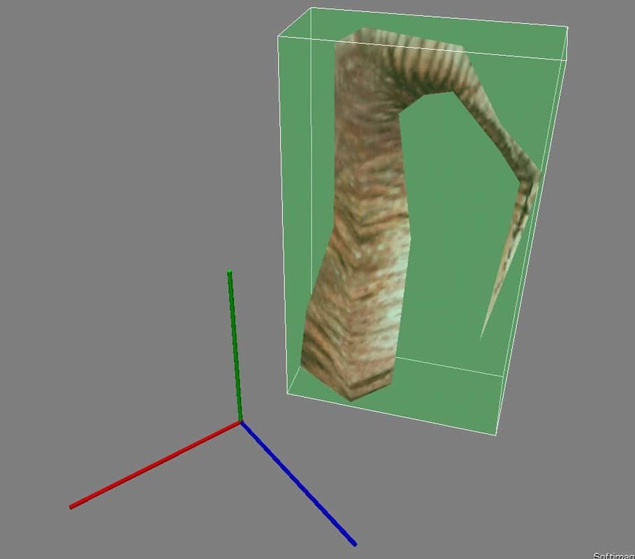
This shows a model which has no rotations on its local axis. The bounding box fits a little more naturally than below. For an Object Aligned Bounding Box system it would look the same since the model has no local rotation.
Here the Model has now been rotated about 45 degrees. The bounding box for an Axis Aligned system simply grows to encapsulate the whole model.
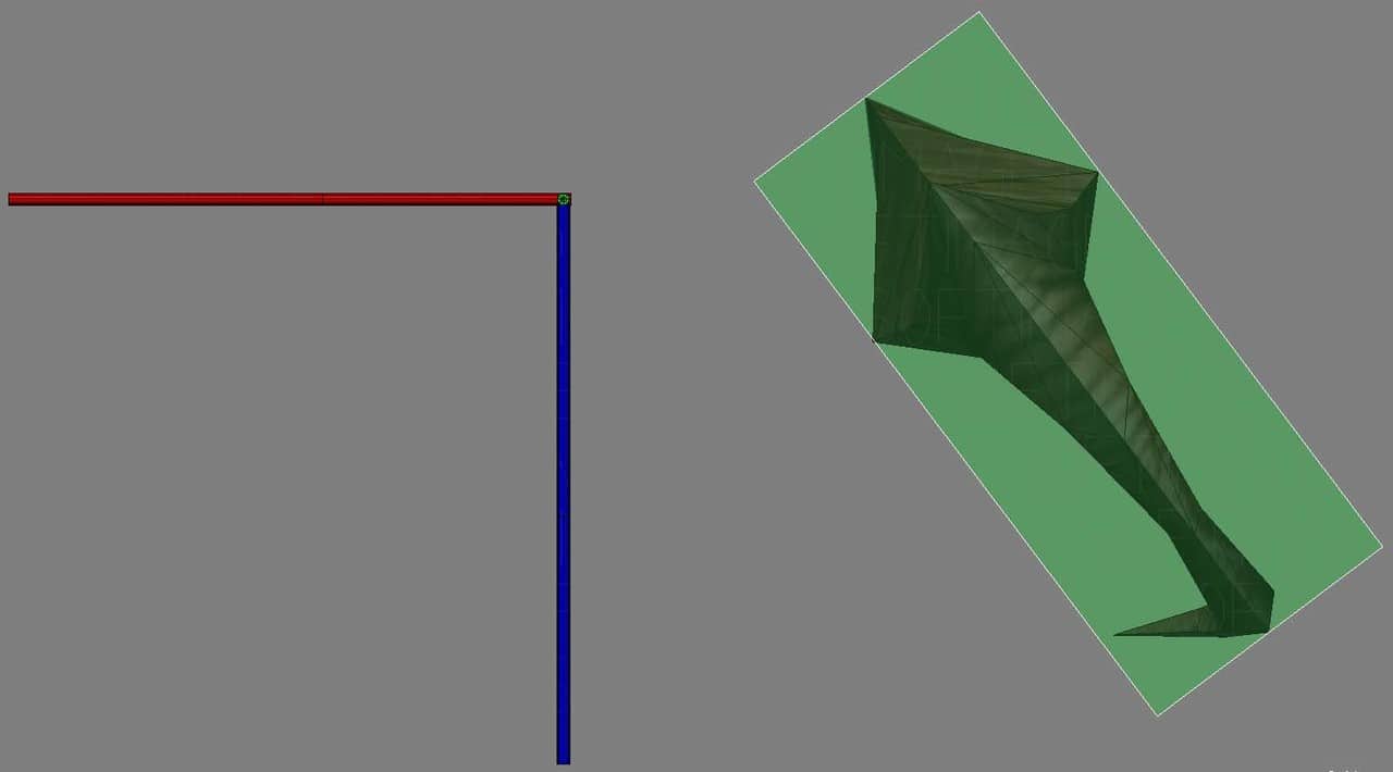
Here is what would happen on an OOBB system. The bounding box would follow the orientation of the model and would not stay locked to the world, and as a result it wouldn’t grow like it does in the AABB solution. This would be a nice system to have in GoldSrc but unfortunately it is not implemented and for the purposes of my mod it wouldn’t warrant an attempt to implement it. So for now we are stuck with AABB Collisions.
From what I have observed and learned of GoldSrc’s collision system is it depends greatly on how the entity that loads the model handles the size of the collision box. Either it will take the sizes set by the animation loaded by the model (if any) or you can set a size through code.
Rotations are going to cause an issue simply because the bounding volumes cannot be rotated in an AABB system. This means that if we want our model to be completely encapsulated in a bounding volume it will be a very inaccurate representation of the already inaccurate collision box. To combat that I suggest we set a manual bounding volume for any static meshes we place and that we reduce the size and position of this box to underlap the model itself. Some clipping will occur in some cases but it would provide a better collision volume. We will explore this further on in the tutorial using the Xen Tree as our example model.
In our case what we will do is provide the user with an option to load the bounding box from the models currently running animation sequence which it will get from the mdl file itself or the user can manually enter a static size in hammer.
Hardcoded Bounding Volume
UTIL_SetSize(Entity, Vec3 Mins, Vec3 Maxs)
It accepts a reference to the entity whose collision size you are setting, as well as two Vector 3 Objects for the Minimum XYZ Position and the Maximum XYZ Position of the Collision box.
In our Spawn Function lets add the following:
pev->solid = SOLID_BBOX;
UTIL_SetSize(pev, Vector(-32, -32, 0), Vector(32, 32, 32));
//                 Mins    X    Y  Z    Maxs   X   Y   Z
pev->solid must be set to SOLID_BBOX otherwise we will still be able to walk through it even with UTIL_SetSize() set. We will make this a selectable Flag in Hammer for those who want to clip static meshes.
Other Flags this can be set to include:
#define SOLID_NOT  0 // no interaction with other objects
#define SOLID_TRIGGER  1 // touch on edge, but not blocking
#define SOLID_BBOX  2 // touch on edge, block
#define SOLID_SLIDEBOX 3 // touch on edge, but not an onground
#define SOLID_BSP  4 // bsp clip, touch on edge, block
For the UTIL_SetSize() function note that you can set the mins to a negative value. Compile the Code and enter your test level once again. You should notice that when you try to walk through your mesh the player steps up slightly. That is because we made a square 64W * 64L * 32H at the models origin. We set the mins Z to 0 to avoid the volume clipping downwards through the worlds ground.
To briefly explain how the min and max values are used to create a bounding volume, see the following description.
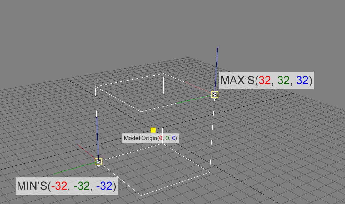
UTIL_SetSize(pev, Vector(-32, -32, -32), Vector(32, 32, 32));
Bounding boxes for models in GoldSrc are bound to the local position of the model. So in the case above where we provide Mins of -32, -32, -32 that means -32 units on all axis from the models local 0,0,0 position, not the models world position. The Maxs are 32, 32, 32 on all axis which means +32 on all axis from the models local position.
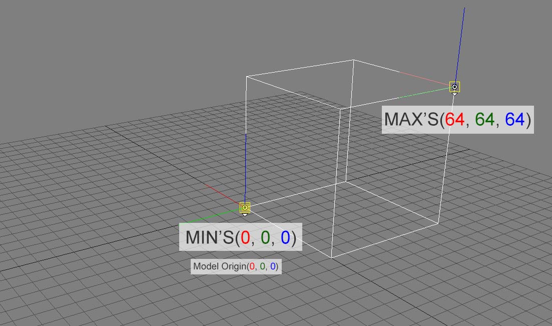
UTIL_SetSize(pev, Vector(0, 0, 0), Vector(64, 64, 64));
Here we set the Mins to 0, 0, 0 which is the same as the models local position and the Maxs to 64, 64, 64 along each axis. This in most cases (unless the model is offset) will give for an undesirable amount of collision coverage as only a quarter of the model (depending on the models shape) would be covered.
GoldSrc then takes the Mins and Maxs and constructs a Cube from the given value.
Visualizing the Collision Volume
Add the following function to our Util.h file:
void UTIL_RenderBBox(Vector origin, Vector mins, Vector maxs, int life, BYTE r = 0, BYTE b = 0, BYTE g = 0);
And then add the function to the end of util.cpp
void UTIL_RenderBBox(Vector origin, Vector mins, Vector maxs, int life, BYTE r, BYTE b, BYTE g)
{
 //********************Render boundrybox**************************

 MESSAGE_BEGIN(MSG_BROADCAST, SVC_TEMPENTITY);

 WRITE_BYTE(TE_BOX);
 // coord, coord, coord boxmins
 WRITE_COORD(origin[0] + mins[0]);
 WRITE_COORD(origin[1] + mins[1]);
 WRITE_COORD(origin[2] + mins[2]);

 // coord, coord, coord boxmaxs
 WRITE_COORD(origin[0] + maxs[0]);
 WRITE_COORD(origin[1] + maxs[1]);
 WRITE_COORD(origin[2] + maxs[2]);
 WRITE_SHORT(life); // short life in 0.1 s (1min)
 WRITE_BYTE(r); // r, g, b
 WRITE_BYTE(g); // r, g, b
 WRITE_BYTE(b); // r, g, b

 MESSAGE_END(); // move PHS/PVS data sending into here (SEND_ALL, SEND_PVS, SEND_PHS)
}
After that, we will need an update function which GoldSrc presents to us through the Think Function.
Note: If you want your model to update on a frame by frame (or a custom amount) basis you will need a Think function. We can set this function using the SetThink(&ReferenceToCustomThinkFunction). We will be setting Animate(void) as the Think Function for our Mesh Loader Class.
Add the Animate function to the header file.
class CStaticMesh : public CBaseAnimating
{
private:
 void Spawn(void);
 void EXPORT Animate(void);
};
Note: If I remember correctly the EXPORT Macro is used to export the symbols to the DLL such that the game can query its state between save games. Functions that use this are SetThink, SetUse, SetTouch, SetBlocked. When we save a game in GoldSrc, the Engine is queried for the symbolic name for these functions, when we load the save game the Engine simply has to look up this symbolic name and restore the state.
Let’s add this Animate function to the source CPP file. Simply add it after void CStaticMesh::Spawn(void)
void CStaticMesh::Animate(void)
{
 pev->nextthink = gpGlobals->time + 0.01;
UTIL_RenderBBox(pev->origin, pev->mins, pev->maxs, 1, 0, 255, 0);
}
pev->nextthink is basically a time in the future when you will call the Think Function again for this Class which in this case is Animate. We set pev->nextthink to the current time plus 0.01. Adding a larger number to the end would mean that the animate function would be re-called less frequently and the opposite for an even smaller number.
The function we added earlier will provide a visual representation of our bounding box.
UTIL_RenderBBox(Entity, Mins, Max’s, Lifetime, ColorR, ColorB, ColorG);
This function accepts a reference to our Entity, The Mins and Maxs of the box you want to render (we provide the same mins and maxs we gave the Bounding Box).
The Lifetime controls how long the representation renders for. (doesn’t seem to work as expected) The last three parameters control the RBG values of the visualization (yes that’s right RBG not RGB)
We have one further change to make to our Spawn() function in order to enable our Think function. Add the following at the end of the Spawn function:
SetThink(&CStaticMesh::Animate);
pev->nextthink = gpGlobals->time + 0.01;
Here we set our local Animate function to be used as the Think Function by the Engine. Again we set the next think slightly into the future. In this case it is only called once as it’s the spawn function, The Animate function will henceforth handle all updates.
Compile your code and run the game. You should see something like this:
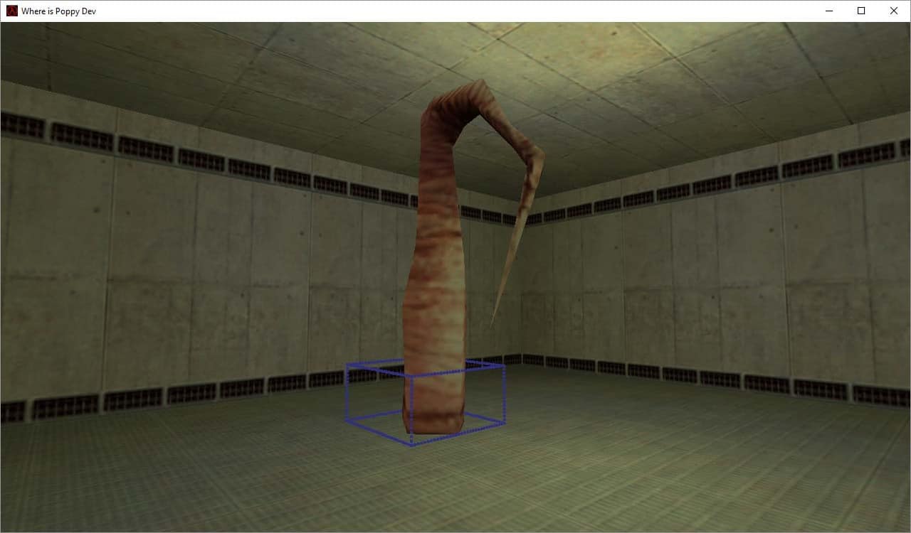
Now if I was to change the Mins in the UTIL_SetSize to 0,0,0 like so:
UTIL_SetSize(pev, Vector(0, 0, 0), Vector(32, 32, 32));
Observe the affect it has on the Collision Volume:
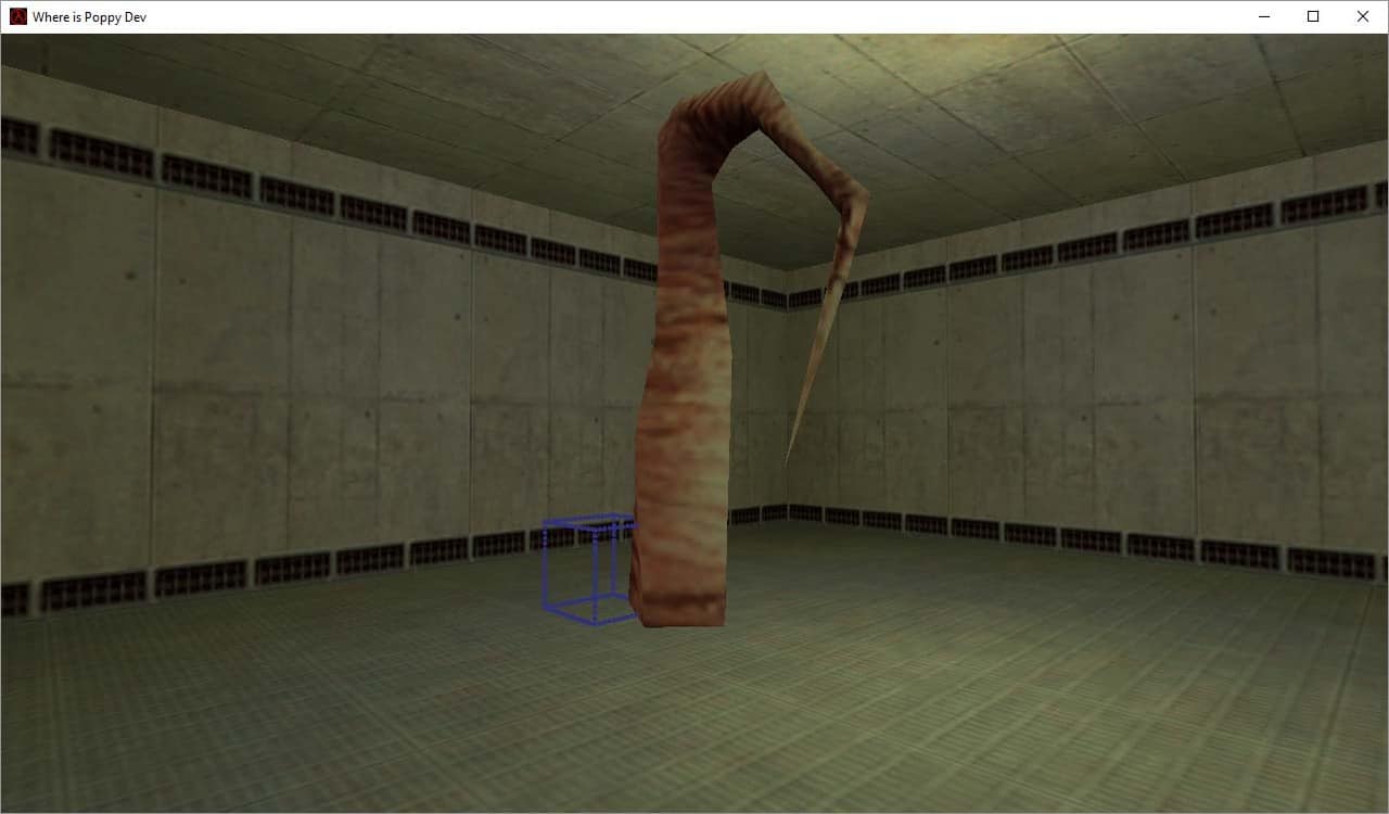
It may look like the bounding volume is rendering down the negative axis but in fact recall that we had rotated our model 180 degrees. The bounding volume is not at all affected by the rotation of the Mesh. So with that in mind notice that the Mins are positioned exactly on the pivot or root of this model.
You will need to keep in mind that if you want your model encapsulated by your collision mesh set at least the X and Y values of the Mins Vector to the negative version of the Max’s X and Y Vector.
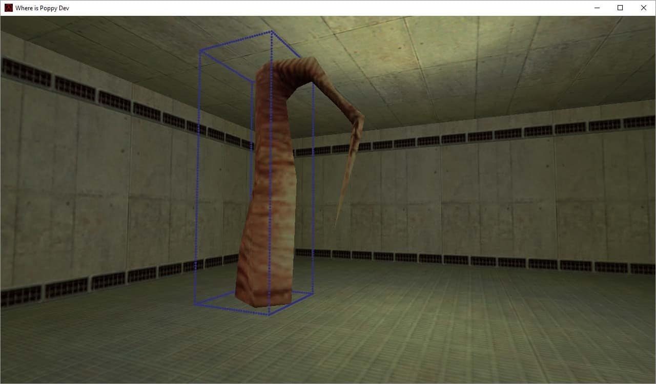
A suitable Value I see for this particular Model is the following:
UTIL_SetSize(pev, Vector(-32, -32, 0), Vector(32, 32, 190));
The next step is to make this currently static function a little more modular so that the user can set the Min and Max values in Hammer and have those values used on object spawn.
Manually set Collision Volume
void KeyValue(KeyValueData *pkvd);
Vector mins, maxs;
The Header should now look like this:
class CStaticMesh : public CBaseAnimating
{
private:
 void Spawn(void);
 void EXPORT Animate(void);
 void KeyValue(KeyValueData *pkvd);
Vector mins, maxs;
};
KeyValue will be the function to read specific non standard elements from the compiled Map for use in our entities code. We also declare Vector variables for our min and max values so that we can modify and set them between functions in our class. Next we must modify our Spawn function once again.
We must replace our UTIL_SetSize() Function
UTIL_SetSize(pev, Vector(-32, -32, 0), Vector(32, 32, 190));
with:
UTIL_SetSize(pev, maxs, mins);
The whole Spawn function should now look like this:
void CStaticMesh::Spawn(void)
{
 PRECACHE_MODEL((char *)STRING(pev->model));
 SET_MODEL(ENT(pev), STRING(pev->model));

 pev->solid = SOLID_BBOX;
 UTIL_SetSize(pev, mins, maxs);

 SetThink(&CStaticMesh::Animate);
 pev->nextthink = gpGlobals->time + 0.01;
}
Next up let’s make the KeyValue Function. You can add it anywhere in your CPP file.
void CStaticMesh::KeyValue(KeyValueData *pkvd)
{
 if (FStrEq(pkvd->szKeyName, "bbmins"))
 {
  UTIL_StringToVector(mins, pkvd->szValue);
  pkvd->fHandled = TRUE;
 }
 else if (FStrEq(pkvd->szKeyName, "bbmaxs"))
 {
  UTIL_StringToVector(maxs, pkvd->szValue);
  pkvd->fHandled = TRUE;
 }
 else
  CBaseEntity::KeyValue(pkvd);
}
Basically this function is called before our spawn function to gather values set inside our map. We will need to make changes to our FGD and map shortly.
We are setting the min Vector to a string value which will be set on the “bbmins” FGD Key. The same will happen to the maxs Vector which will be set to the “bbmaxs” key value.
We use a very useful function to convert a string to a vector called UTIL_StringToVector(Vector, String) It turns the String “32 64 51” into the Vector(32, 64, 51) Add bbmins and bbmaxs to our FGD file with default Values.
// Where is Poppy Forge Game Data
// Cathal McNally
// sourcemodding@gmail.com
// www.sourcemodding.com

// February, 2017

// wip_StaticMesh

@PointClass color(0 255 0) size(-20 -20 -20, 20 20 20) studio() = wip_StaticMesh : "wip_StaticMesh"
[
 model(studio) : "Model"
 bbmins(string) : "Collision Volume Mins" : "-16 -16 -16"
 bbmaxs(string) : "Collision Volume Maxs" : "16 16 16"
]
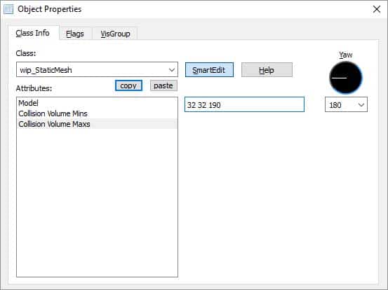
Restart Hammer and open the properties for our wip_staticMesh Entity.
Add 3 space separated Values to the Collision Volume Mins Parameter. “-32 -32 0”
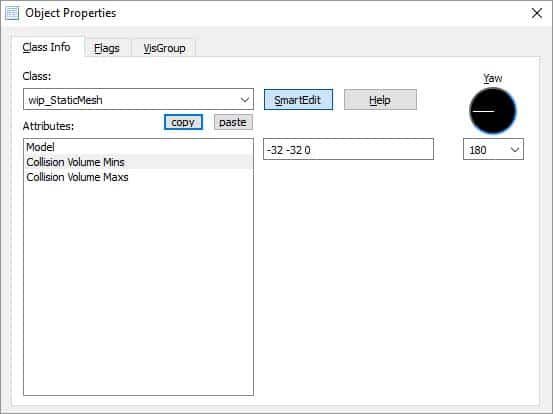
Add 3 space separated Values to the Collision Volume Maxs Parameter. “32 32 190”
Compile the Map and the Code. Then run the Game to see your bounding box using the values you input through Hammer.
Solid Flag
Firstly, let’s add the following to our header:
#define WIP_IS_SOLID 1
This will be used as an identifier to check if the first flag set on the properties is true or false. If this was set to 2 we would be checking the second flag etc.
Next is to make some changes in our spawn function. We must wrap a condition around our pev->solid and UTIL_SetSize lines.
It will look like this:
if (FBitSet(pev->spawnflags, WIP_IS_SOLID))
{
 pev->solid = SOLID_BBOX;
 UTIL_SetSize(pev, mins, maxs);
}
This checks the boolean state of the given Flag. In this case we are passing the first flag and only if it’s true will the entity be set to solid and a size set.
The last thing we need to do to make this work is to add the spawnflags to the FGD
spawnflags(flags) =
[
    1: "Solid?" : 1
]
The “1” key above corresponds to the 1 we set WIP_IS_SOLID to. “Solid?” is what the flag will be called in hammer. The last “1” is the default value which in hammer will translate to true.
Save the FGD and restart Hammer to load in the new FGD Values.
There should be a new flag on the Flags tab of the wip_staticMesh properties.
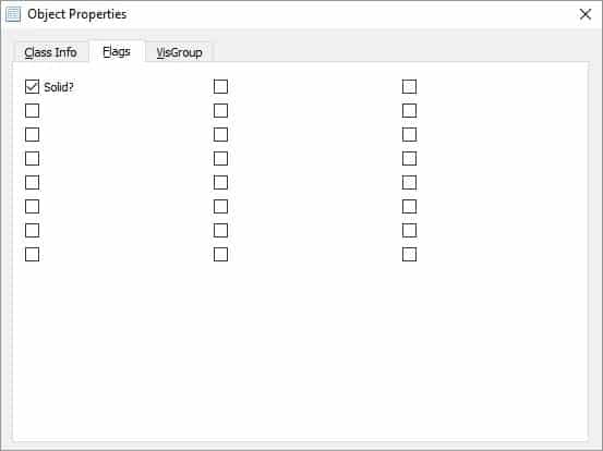
Set it to true, compile the map, compile the code and test your level. You should still be blocked by the collision box.
Set it to false and you should be able to pass clean through your model.
Sequence based Collision
Firstly, lets add this to our header.
unsigned short m_iCollisionMode;
Note: I made this a short because it is cheaper than a full integer type, and unsigned because it should never be a negative value.
It will be used for a multi choice selection within Hammer and then checked in our spawn function upon which we will use either a sequence based collision box or our previously added manual values for a collision box.
The function used to set our mins and maxs from a sequence is:
ExtractBbox(Sequence Number, mins, maxs)
This function will look up the local entity that owns the current instance of the class, grab the sequence that we set as an integer and populate two Vectors which in this case will be mins and maxs.
In our Spawn function let us change this:
if (FBitSet(pev->spawnflags, WIP_IS_SOLID))
{
 pev->solid = SOLID_BBOX;
 UTIL_SetSize(pev, mins, maxs);
}
To:
// Check if the Solid Flag is set and if so be sure to set it
// solid with appropriate Collisions
// If not we also do not set a Collision Box because for a static mesh
// there is no reason to do so..
if (FBitSet(pev->spawnflags, WIP_IS_SOLID))
{
 pev->solid = SOLID_BBOX;

  if (m_iCollisionMode == 1)
 {
  UTIL_SetSize(pev, mins, maxs);
 }
 else if (m_iCollisionMode == 2)
 {
  ExtractBbox(0, mins, maxs);
  UTIL_SetSize(pev, mins, maxs);
 }
}
Note that we are setting the sequence to 0 here, we will be providing a future option shortly for users to input what sequence they want their model to play.
Then we must modify our KeyValue function to read in a value for m_iCollisionMode
Change the following:
void CStaticMesh::KeyValue(KeyValueData *pkvd)
{
 if (FStrEq(pkvd->szKeyName, "bbmins"))
 {
  UTIL_StringToVector(mins, pkvd->szValue);
  pkvd->fHandled = TRUE;
 }
 else if (FStrEq(pkvd->szKeyName, "bbmaxs"))
 {
  UTIL_StringToVector(maxs, pkvd->szValue);
  pkvd->fHandled = TRUE;
 }
 else
  CBaseEntity::KeyValue(pkvd);
}
To include it:
void CStaticMesh::KeyValue(KeyValueData *pkvd)
{
 if (FStrEq(pkvd->szKeyName, "collisionmode"))
 {
  m_iCollisionMode = atoi(pkvd->szValue);
  pkvd->fHandled = TRUE;
 }
 else if (FStrEq(pkvd->szKeyName, "bbmins"))
 {
  UTIL_StringToVector(mins, pkvd->szValue);
  pkvd->fHandled = TRUE;
 }
 else if (FStrEq(pkvd->szKeyName, "bbmaxs"))
 {
  UTIL_StringToVector(maxs, pkvd->szValue);
  pkvd->fHandled = TRUE;
 }
 else
  CBaseEntity::KeyValue(pkvd);
}
Lastly we need to add our multi-option to our FGD.
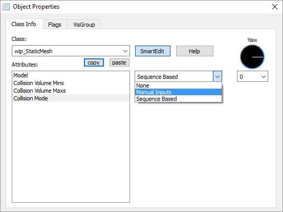
collisionmode(choices) : "Collision Mode" : 2 =
[
 0: "None"
 1: "Manual Inputs"
 2: "Sequence Based"
]
Save your FGD and restart hammer.
You should now see a multi-option choice box as part of the entities properties.
I then setup two entities in hammer one using Manual Inputs where I use Mins of (-32, -32, -32) and Maxs of (32, 32, 32) so our collision box should be a distinctive cube.
The other entity will use sequence based collision and as we have set the sequence to 0 in the code it will use this models first sequence as a collision box.
Note: It’s important to remember that if the Solid Flag is not set in the Flags tab, no collision values will work and no collision box will be set even if you set the values here. This is used to optimize spawn times for static meshes that do not require collision volumes.
This is how it looks.
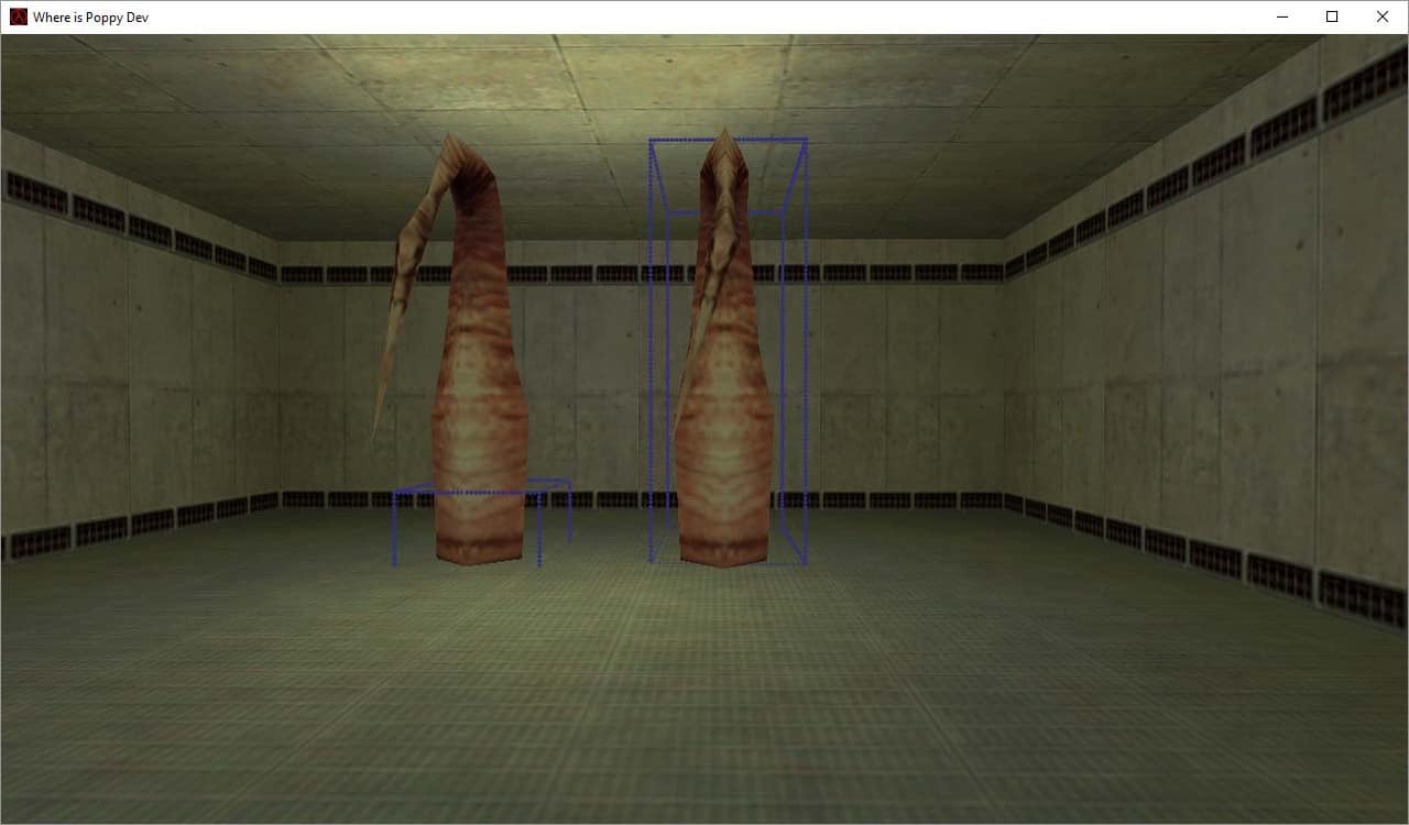
The tree to the left uses the manually set collision while the tree to the right uses the models first sequence bounds as a collision volume.
The Issue of Rotation and Collisions with an AABB System
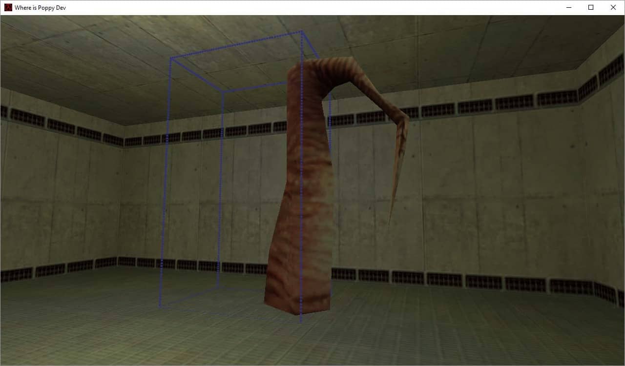
As you can see above the bounding Volume does not rotate with our model which has been rotated 180 on the z axis. The best solution to this would be to implement OOBB Collisions but that is far beyond the scope of this tutorial and is honestly not required.
I propose using manual inputs for bounding volumes on models of these type. Consider this:
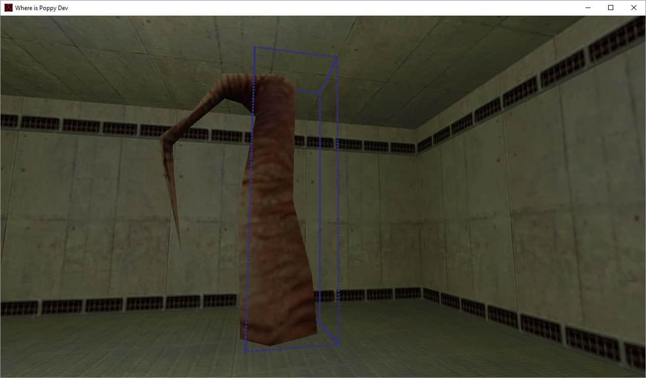
Create a tall volume centred around the models pivot so that when the model rotates the main shaft of this particular model is covered. It’s not perfect but AABB is far from a perfect collision system, we work with what we have.
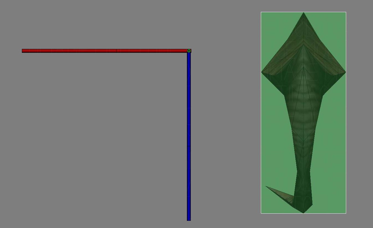
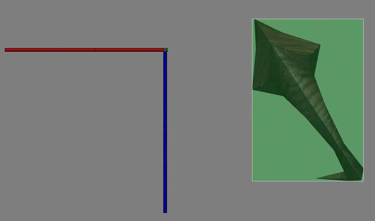
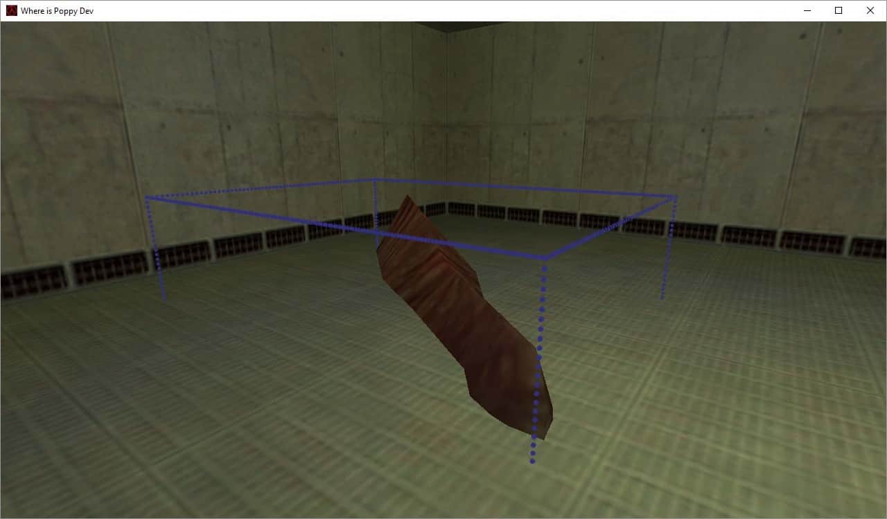
Consider a model that is longer in width or length than it is in height. I will rotate the tree model on its side to demonstrate this. You could not use the sequence based collisions at all, you can use the manual inputs for angles that are multiplies of 90 degrees.
I rotate the model in hammer with the following values.
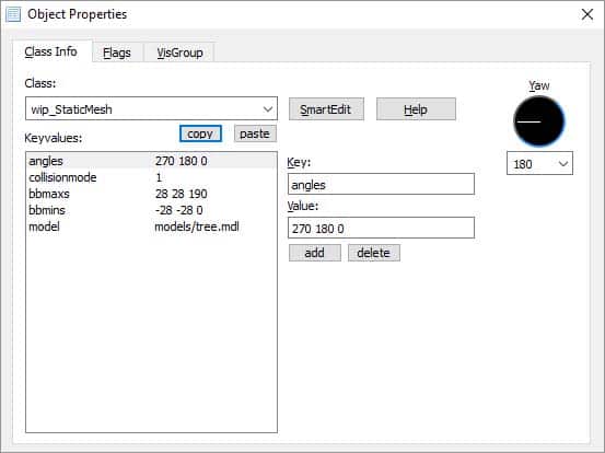
It then looks like this:
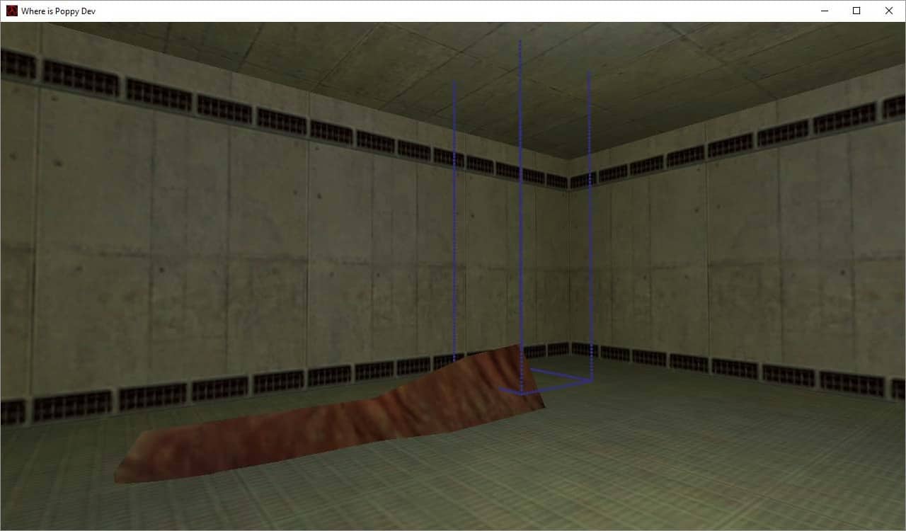
I then set the Mins to -190 -28 -28 and the Maxs to 0 28 28 and the result can be seen below.

If I rotate the model 90 degrees, I would need to update the mins and maxs to cover it again. So long as the models local orientation looks directly down one of the world’s axis you will be able to make some sort of useable collision volume for it.
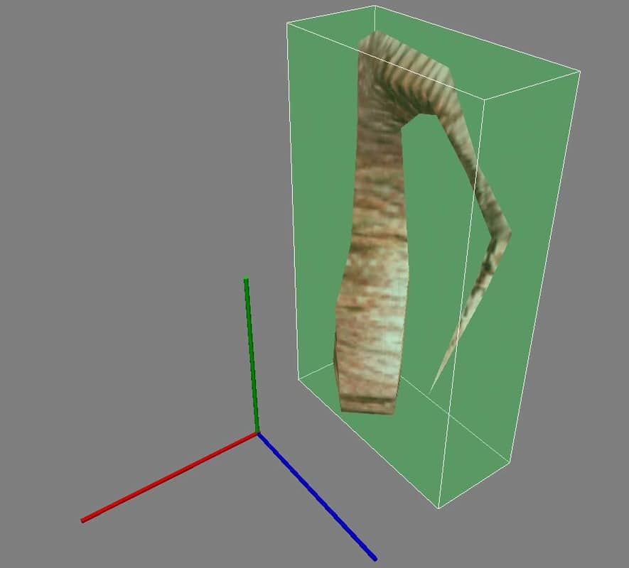
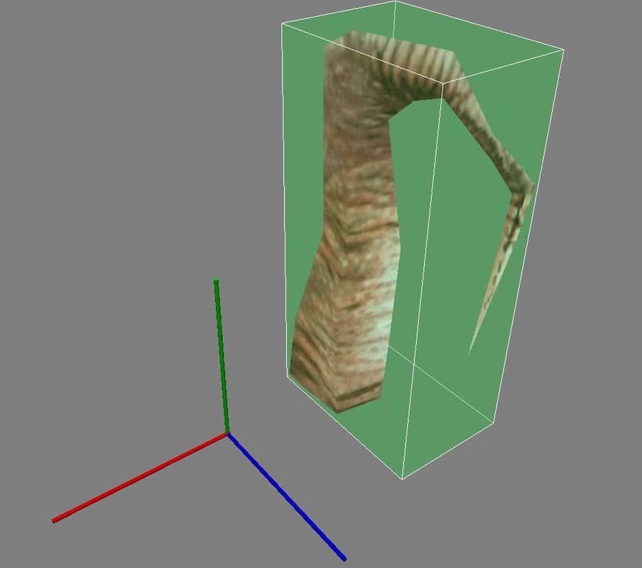
However, when the model is rotated anywhere between 90 degree steps you have the following issue when you update the mins and maxs to cover the model.
The mins and maxs used to get this are: Mins -130 -145 -28 Maxs 0 28 28
And as you can see it is a woefully inaccurate collision box.
To work around this, I propose you disable collision on a model with these rotations and orientation and use invisible BSP geometry (CLIP Brush) to build smaller colliders along the model which is assumed to be static.
They would look something like this:
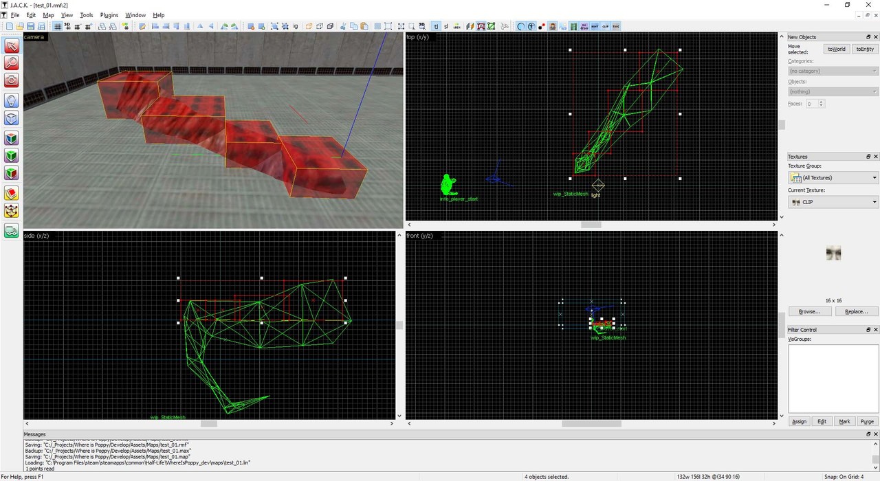
The CLIP Brush is basically a static block with the CLIP Material applied to it. It renders the geometry with the Material applied to it as invisible but prevents the user from walking through it, similar to “player clip” in Source.
It’s obviously far from a perfect solution but it’s a decent workaround.
Keep in mind that you could always use a CLIP brush instead of manually entering Mins and Maxs for the models own collision model.
Bounding Box Visualization Aid
Let’s first add another Flag to our header and set it to 2 (The second flag in the Flags Tab) and a Boolean that we will use in our animate function to enable or disable the bounding box visualizer.
bool m_bDebugBB = false;

#define WIP_DEBUG_BB 2
Next change the following in our spawn function:
if (FBitSet(pev->spawnflags, WIP_IS_SOLID))
{
 pev->solid = SOLID_BBOX;

 if (m_iCollisionMode == 1)
 {
  UTIL_SetSize(pev, mins, maxs);
 }
 else if (m_iCollisionMode == 2)
 {
  ExtractBbox(0, mins, maxs);
  UTIL_SetSize(pev, mins, maxs);
 }
}
To this:
if (FBitSet(pev->spawnflags, WIP_IS_SOLID))
{
 pev->solid = SOLID_BBOX;

 if (m_iCollisionMode == 1)
 {
  UTIL_SetSize(pev, mins, maxs);
 }
 else if (m_iCollisionMode == 2)
 {
  ExtractBbox(0, mins, maxs);
  UTIL_SetSize(pev, mins, maxs);
 }

if (FBitSet(pev->spawnflags, WIP_DEBUG_BB)){
  m_bDebugBB = true;
 }
}
We do the WIP_DEBUG_BB check within the WIP_IS_SOLID check because we don’t need to visualize the bounding box when our model won’t be solid.
We carry out the flag check in the spawn function and set the Boolean m_bDebugBB to true. We do this because it’s cheaper than doing an FBitSet check in our animate function every frame. This way we will only have to check the Boolean value every time the animate function is called.
Change the Animate function from:
void CStaticMesh::Animate(void)
{
 pev->nextthink = gpGlobals->time + 0.01;
 UTIL_RenderBBox(pev->origin, pev->mins, pev->maxs, 1, 0, 255, 0);
}
To:
void CStaticMesh::Animate(void)
{
 pev->nextthink = gpGlobals->time + 0.01;
 if (m_bDebugBB){
  UTIL_RenderBBox(pev->origin, pev->mins, pev->maxs, 1, 0, 255, 0);
 }
}
Then in the FGD add the “Debug Bounding Box?” flag to our spawnflags:
spawnflags(flags) =
[
 1: "Solid?" : 1
 2: "Debug Bounding Box?" : 0
]
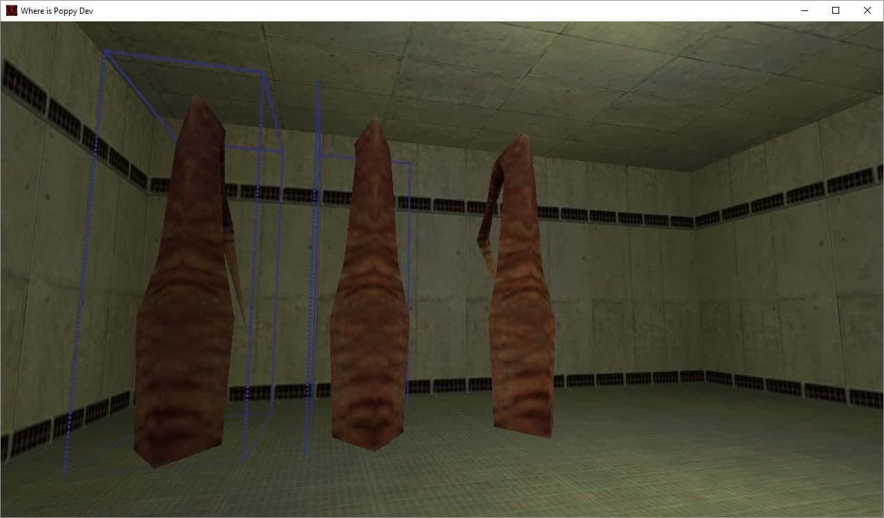
Note: The UTIL_RenderBBox function seems to be limited in how many lines it can render, Probably an engine limit. See the following screen shot to explain what I mean; I have multiple entities loaded in the map with the WIP_DEBUG_BB Flag set to true. The last model (rightmost) I added does not render any Bounding Box Visualization and the second model (middle) only renders some of the lines of the Bounding volume.
r_drawentities 5
- Don’t render any entities
- Default, Render an Entity in its normal state
- Render an Entities Skeleton if it has one
- Render an Entities HitBoxes
- Render an Entities Hitboxes translucent with the Model underneath
To enable this feature in the OpenGL Renderer we have a small change to make to StudioModelRenderer.cpp
Locate the StudioRenderFinal_Hardware Function and add the following condition:
// Lets add bounding boxes to the OpenGL Renderer too!
if (m_pCvarDrawEntities->value == 5)
{
 IEngineStudio.StudioDrawAbsBBox();
}
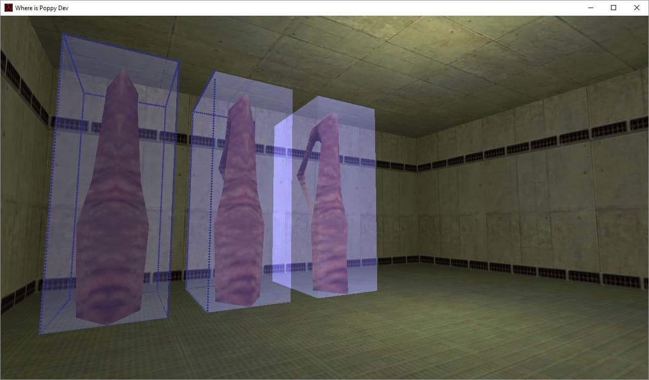
You can see that I borrowed it directly from the StudioRenderFinal_Software function. As to why this was exclusive to the Software Renderer I do not know but I suspect it was simply not supported by OpenGL in the late 90’s. You can compile the code and enter r_drawentities 5 to see the transparent blue representation of the currently selected sequence Bounding Box (Remember that we hardcoded it to 0 earlier as part of our ExtractBbox function)
Part 2
Due to the monstrous size of this tutorial and the styling applied I had to split it into two parts because of Moddb's 100000 Character Limit.
You can Read the second part here.
You can read the complete tutorial over at Sourcemodding.
You can Read the second part here.
You can read the complete tutorial over at Sourcemodding.


Holy Sh&/%(t
This is going to help a lot of people, nice tutorial!
Thanks :D I hope it does!
I have a question Can you make a mod without c++ ? or other programing things ?
No, can't.
Can I use "codeblocks" instead of visual studio?
Huh, a lot of work for that very simple entity. Anyways, the tutorial is great!
It is, almost too much effort, I see coding for HL these days more of an artform :)
Thank you for the kind words :)
Working on the next installments.
This was very helpful, but I can't find StudioModelRenderer.cpp item