Originally posted here: Stargatecommand16659.yuku.com
Created by: MaLuS
Mirrored here for archival purposes
Note this tutorial exceeds Moddb's maximum article length. I will produce a part two of it.
Dedit Tutorial part 1
Hey guys and gals this is for all of you that wish to learn (or remind yourself) how to use Dedit to make maps for AVP2.
If you are looking for something specific then you might find this link useful Modmakers Dedit Tutorials
If you are starting out for the first time and want to learn I would advise you follow this tutorial below and mapping mapping!
Welcome to the DEdit overview and tutorial. DEdit is the tool created by the LithTech team that enabled the AVP2 Level Designers and Artists to create the geometry and gameplay you experienced in Alien vs Predator 2 (AVP2). DEdit allows you to build the ground, sky, walls, ceilings and shapes for your levels. You will then apply textures, props, prefabs, lights and sounds to give them a realistic appearance. Alien vs Predator 2 was created using literally thousands of these assets which you may appropriate to create the base for your own level. You may also add your own assets where applicable. Finally, you’ll add the game objects that allow other players to interact with your world.
Creating levels is an extremely complex and time consuming process, and the following is merely the starting point for those who want to learn the basics of building worlds for the LithTech engine. If you’ve done game design before on a 3D or near-3D game, you’ve probably worked with tools like DEdit. A separate document will cover ModelEdit, the companion to Dedit, that allows you to create characters and models for your world.
Basic Terms
These terms are relevant to a discussion of DEdit.
Project — A project in DEdit represents the sum of all the resources in the game: all the code, all the textures, all the sounds, all the worlds, and so on. Unlike other world geometry editors, DEdit first opens the project, rather than a world file.
World — When your players walk around in your game, it is a world that they’re standing in. Worlds divide your game up into sections where different parts of the game take place. In other games, these are sometimes referred to as maps, levels, scenes, or episodes. World-editing is the primary focus of DEdit and each world is stored in a separate file on the hard drive.
Objects — Simply put, anything a player interacts with that moves, lights up, shoots, growls, or goes into the player’s inventory is an object . DEdit allows you to place any kind of object that your game’s code or the engine’s code can create.
World Geometry — Parts of the world that act as walls, floors and sky are generally made of world geometry . Such geometry is solid, immovable, and generally never changes.
Brush — The basic unit of world geometry. A brush is made up of planes that define its faces, lines that define its edges, and vertices that define its corners. All brushes must be convex for reasons that will be discussed later. You can manipulate either an entire brush at once or any of the vertices, lines, or planes in the brush.
Primitive — A simple shape that you can add to the world as the foundation of a more complex shape. Typical primitives are things such as cubes, pyramids, and cylinders.
Prefab — A prefab is like a primitive, but more complex. If you build a street lamp complete with textures and a light source that gives off just the right shade of light, you can select the lamp and its associated source (or any group of objects and brushes inside DEdit) and save it as a prefab . Thereafter, you can copy and paste that streetlamp into your world without having to rebuild the whole object.
Unit — The basis of measurement in DEdit and the LithTech engine. Units don’t equate directly to real-world values. Instead, the game designers can select a scale of game units to real-world measurements. As an example, in Alien vs Predator 2 the following values are used: railings are 48 units tall, a chest-high box would be 64 units, and a typical doorway would be 128 units high.
Mode — DEdit has several different modes that allow you to change certain elements of your world (i.e. just brushes or just objects) without accidentally affecting others. They’re designed to simplify interacting with your world while editing, so it’s important to choose the right mode for your task.
Processing — When you process your world, DEdit creates a second version of the world with some information removed (parts only you need to know about), and other information added (parts only the game engine needs).Processing is a necessary step you’ll take in getting your world up and running in the game, and is often the first place where you will discover problems with your level.
Texture — In DEdit, textures are used like wallpaper, paint, or plaster to cover the raw plywood of your walls, floors, ceilings, doors and so forth. Without a texture, your brush will appear flat-shaded in the game, almost always with unpleasant results. Just as you wouldn’t want a house with raw plywood walls, you always want to apply textures to the brushes in your level.
Building Your First World
The first step we’ll want to follow in building our new world is to pick a project. As mentioned above, a project specifies all the resources you’ll have access to in your world, from the game code on up. Generally, you’ll only create or use one project per game. Projects can be modified over time very easily, since they simply consist of a collection of files laid out on disk in a structure that DEdit can recognize.
In the File menu select the Open Project command or press CTRL+O . Navigate to the directory in which you have installed AVP2, you’ll notice that DEdit lists a .dep file. This is the project’s root file, and it stores various tidbits about the project. This is the only type of file you will directly open with DEdit.
Now that you have your project open, you’ll want to create a world to work in. This is also easy to do. Go to the File menu and select New World . When DEdit asks you what to name the world, type “Simple1”. This is the name your world will have when you go to open it in DEdit.
Tip: The name you provide is also the name of the world’s file on your hard drive (Simple1.ed ). Later we will cover how the project is written to your hard drive.
The DEdit User Interface
What you see in front of you will look similar to this:
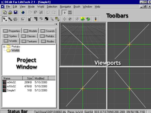
The callouts in this screenshot illustrate the various sections of DEdit’s UI. Use the buttons in the Toolbars to make new worlds, switch modes, and run your world. You can learn an individual button’s function by hovering your mouse over it to get a Tool Tip.
In the Project Window , DEdit gives you access to all of the resources in the game. Most tabs represent a resource you can add to the game. There are two special ones ( Properties and Nodes ) that relate to objects inside your maps. We’ll discuss all of these in a later section and they’re documented in the DEdit Toolbars chapter as well.
There are four viewports that provide windows onto the world you’re building. Each one presents a different view of the world. The upper left window shows you a Perspective view shot from a movable camera point in the level. The other three views have a fixed-view camera that displays either Top, Front or Left view (going in clockwise order). You’ll spend a lot of time working with these views.
In the Status Bar , DEdit provides information about the level or about the view you’re currently in. We’ll get into the depths of the user interface in later chapters, although you’re welcome to stop and explore if you’d like. Use the Tool Tips and the Status Bar to learn more about what the controls do.
Making a Simple Room
Our first world is going to be very, very simple. We’re going to make a box with a light. If you’re a programmer, this may be as complex of a level as you need to create, since you’ll mainly be making levels only to test your code and not for inclusion in the game itself.
Even though this level is extremely simple, we’ll still want to texture it. Use your mouse to select the Textures tab in the Project Window . This tab is where you select textures to apply to your brushes. In the top section of theTextures tab, there’s a box with folders listed in it. Click on the folder that is called WorldTextures.
When you do so, the list box in the middle of the tab should fill up with subfolders that break the textures up into categories. Within these subfolders there is a folder called Floor_Ceiling. Within these folders are listed the individual texture names. Click on the folder called Floor_Ceiling. In the list of textures choose a texture named asphalt. Notice that there’s a preview of Asphalt in the bottom window of the tab. From now on (until you select a different texture) this texture will be applied to every brush you create.
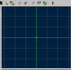
To actually start putting brushes into your world, first move your mouse pointer over the upper-right-hand viewport (top view). The green crosshairs (also called the marker or the insertion point ) is like the cursor in a word processor: it’s where the objects you add to your map (brushes, objects, and things you paste in) will appear. If the viewports are your eyes, then the marker is your hand. We can leave the marker where it is for now, but you’ll learn how to move it around shortly.
The first step, since we’re zoomed in fairly close to the grid, will be to zoom the camera out a little in the viewport so that we can see more of the grid at once. Camera control is done in DEdit using the I, O and C keys with the mouse.
I
In the Perspective View, press I and move the mouse pointer to scroll in the X and Y plane. In all other views, this combination scrolls in all available directions.
I+Left Mouse
Same as above, but faster.
I+Right Mouse
Scroll along the Y-axis in the Perspective View.
O
In the Perspective View, press O and hold the left mouse button to pan the camera in all directions. In all other views, this combination zooms in and out of the displayed geometry.
O+Left Mouse
In the Perspective View, press O and hold the left mouse button to move or “fly” forward through the level.
O+Right Mouse
In the Perspective View, press O and hold the right mouse button to move or “fly” backward through the level.
C
In the Perspective View, press C and move the mouse pointer to adjust the draw distance.
C+Left Mouse
Same as above, but faster.
Press the O key and move your mouse pointer slowly up. You should see the grid in the upper right viewport getting smaller. We’re actually zooming out to see more of our map, not changing the scale of the grid. Don’t zoom out farther than you need to in order to see a few more grid squares on the screen (perhaps four or six squares across the screen). Your screen may be at a high enough resolution that you can already see six or so grid squares. If that’s the case, play with the camera a little but make sure you come back to a scale of about 4-6 squares across.
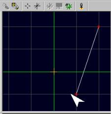
Now press CTRL+B to switch into Brush mode. This is the mode reserved for moving brushes, as well as adding them to the world. From the center of the marker, count up two gridlines and then over to the right by two gridlines. Move your mouse pointer to that intersection in the gridlines. Once you have the mouse over the intersection, press the SPACE key once and move the mouse away. You should now have a line following your mouse pointer.
The line you see is the first side of the brush you’re about to create. To continue the brush, move your pointer until it’s over the grid two gridlines below and to the right of the marker and press SPACE again. DEdit drops the vertex on that point and adds a new vertex and side to the brush. Now move the mouse and place another new vertex four grid units to the left of the current vertex. Add your next vertex four units straight up (two units above the green marker). Last, move the mouse pointer back to the vertex you started at. When you press SPACE over the original vertex, DEdit displays a dialog box that asks you to enter the thickness of your brush. Enter a value of 64 and clickOK . This completes the creation of the brush.
What you see should look like this:
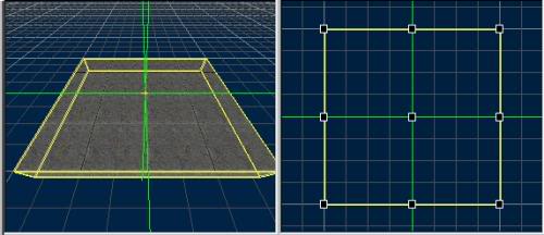
In the 3D Perspective viewport, you can see that your square has been created and given a height of 64 units. This square will form the floor of our simple room. Each time you create a brush in the editor you will be prompted to give it a thickness. The 64-unit thickness was chosen to make the floor brush easy to find in the editor by eye.
Using relatively large units where possible also helps in other ways: You can more often let the editor align your textures for you if you build to the grid, since typical texture sizes fall along the grid as well. If your textures are mostly 32x32, 16x16, 32x64 and so on, laying textures out becomes a very simple task when you build to the grid. You’ll need to scale things to fit much less often, you can more easily make use of textures that tile together and you can realign a texture much more simply. We’ll talk about that in a later chapter as well. For now, assume that building to a large grid where possible is a good rule of level design practice.
Creating a Ceiling
Next, we’re going to use the Copy and Paste feature to create a ceiling for our room. In the Edit menu select the Copy ( CTRL+C ) command. Now there is a copy of the floor brush on the clipboard. Now in the Edit menu selectPaste ( CTRL+V ) to paste. If you look in the perspective viewport (the one in the upper left), you should now see the new brush near your original brush.
Since the brush isn’t lined up quite as you’d want it for a ceiling, you’ll want to move it around a little. In the Top viewport (upper right), press the O key and click the mouse to zoom out until you can see both brushes. Move the mouse to the black drag handle in the center of the brush. Drag handles can be used to move or to resize the objects they’re attached to. In this case, click the left mouse button and drag the center handle towards the center of our original brush (which should still be the center of the marker as well).
When you have the center handle over the marker, your selected brush should be lined up exactly on top of your first brush. Drop the brush there and move your mouse to the bottom right viewport (Front). Use the O key again to zoom the viewport out until you have a good view of the selected brush. Next, click and drag the center handle of the brush until you’ve moved the brush straight up 4 grid units. Don’t worry if that means dragging the brush out of the visible area. The viewport will scroll up for you when you reach its edge.
Your ceiling is now a good height above your floor, at 192 units. That’s about the height of a tall conference room ceiling in most games.
Creating Walls
Now we need to create four walls. In the Front viewport, hold down the X key and move the mouse upwards a few grid lines. What you should see is that the green marker moves wherever you move your mouse. Since the markerrepresents the insertion location where new brushes will appear, we’ll need to move it upwards until it reaches our ceiling in order to add our walls. Move the marker until it’s at the same grid line as the top edge of the ceiling brush.
Now you’ll want to switch back to the Top viewport. Use the O key to zoom out a little further until you can see a few rows of grid around the selected brush. Now use theSPACE bar to draw a rectangular brush that’s 1x4 grid squares and runs along the whole right edge ofyour ceiling brush. When you’re prompted for a thickness, give it a value of 320. That’s a lot thicker than you used for the floor, but there’s a reason. We want this wall to reach all the way from the ceiling to the floor. If you’ll look in the Front view, you’ll see that our new brush does just that, neatly sealing off one side of our room.
To make the next wall, copy and paste your new brush. Then use the center drag handle on the pasted brush to move it until it seals the west side of the ceiling brush the same way that your first brush seals the east side.
Now we have to make two more walls. Using the SPACE bar to draw a 6x1 rectangle on the north edge of the ceiling brush. By making it 6 grid squares wide, you’ll make a good seal against both the floor/ceiling brushes and also against the two existing wall brushes. Make this new 6x1 brush 320 units tall as well.
Note: Sealing a level is another topic that we’ll cover later. For now, accept that it is important.
The last step you’ll need to take making brushes for your level will be to copy your latest brush, paste it and move it to cover the south edge (in the top viewport) of the ceiling brush. Your room now has solid walls, a floor and a ceiling. You’ve created 75 percent of your level.
Adding Objects
There are only three objects left that you need to add in order to see your level: a GameStartPoint (which specifies the location where your player will first spawn into the world), a light (without which you won’t be able to see your level), and a WorldProperties object (which specifies some of the rudimentary information necessary to create your level).
To place your start point, switch to the Front viewport so that you can move the marker vertically. Use the X key to move the marker down until it is one grid square above the floor. You should also check the Top viewport and make sure that the marker (if it isn’t still at the very center of the level) is at least 1 grid square from any of the walls. Since 1 grid square is 64 game units, this ensures that your player won’t accidentally appear halfway into the floor.
Press CTRL+H to enter Object mode. Object mode is the main mode you use for creating, moving, and setting the properties of objects. Once you’re in Object mode, select Add Object from the World menu. In the Objects dialog, the left pane of the dialog lists all the objects that your game code supports. Scroll down the list until you see a “ GameStartPoint ” object. Select it and click OK .
Once you’ve done that, look at the center of the marker. The small white square is the newly created start point. Your player can now actually enter the world.
Now move the marker vertically upward one grid square, using the X key in the Front viewport. Although you could add your light right at the location of the GameStartPoint object, it will be easier to select later if you add it at a different location. In the World menu select Add Object again. This time, go through the list of objects until you find one called Light. Select it and click OK .
Your start point will become unselected, and a small new cube will appear at the center of the marker. You should also notice a bluish circle that surrounds your whole level. That circle represents the radius of the light in the level. The light fades out as it gets further from its center point, and it ends completely at the edge of the blue line. Since you have a small level, one light will illuminate it all without trouble. Lastly, you will need to add a WorldPropertiesobject. Use the X key to move your marker forward one grid square in the Top viewport. As before, select Add Object from the World menu, scroll down, select WorldProperties , and select OK .
Processing the World
The last step you’ll need to take in preparing your level is to process it. In the World menu, select Process and you’ll see a large dialog box appear. The only two checkboxes on the dialog that you need to worry about are Import Geometry and Apply Lighting . The Processor’s options are all documented in the Processor Controls, Options and Parameters chapter, which you can feel free to read now if you want. However, for now only those two boxes must be checked. Don’t worry if the Import Geometry box is grayed out. DEdit is just assuring that the option’s turned on, since the level has never been processed before. You can leave the rest of the checkboxes as they are by default. Once you’ve checked both boxes, click OK to process the level.
The dialog box will change into a progress monitor and a log of what the Processor’s doing. Once an OK button appears in the dialog, your level has been processed. Your world’s now ready for you to explore.
Testing the World
To actually load your level in the game, click on edit, and the options, to bring up the Dedit properties menu. Click on the Run tab. In the Executable field browse to LithTech.exe. In the Working directory enter the location of the root AVP2 directory i.e. C:\AVP2\. In the Program arguments field enter the command string –rez AVP2 +runworld %WorldName% -- please note that this command is case-sensitive, the level will not load correctly in the game unless you match this syntax and character case exactly. After entering all of this you should be able to launch your level by clicking world and the run, by pressing CTRL+ALT+R , or by clicking the Run World button on the tool bar.
LithTech Resource Types
Before starting, you should learn a little more about the structure of the resources that DEdit and LithTech can use in a game. The LithTech engine can access and use a wide variety of file types and other resources. The list below is arranged by resource type, and each resource type includes a list of the sorts of files LithTech can use in that type, as well as a description of those files.
Project — As mentioned before, the project is the total of your whole game and all its resources. A .DEP (DEdit Project) file at the top of your tree of game resource directories serves as a guide to DEdit. The .DEP file is a pointer to the rest of the resources for DEdit and includes some of the information about your game resources. The rest of your game’s files exist in subdirectories of the directory where your .DEP file resides.
Directories — The subdirectories that contain your other game resources are a type of resource in themselves. The structure of these directories defines the tree views you see in many of the tabs in DEdit’s Project window. If you find a game’s .DEP file and look at the subdirectories in the same folder with it, you’ll see names such as TEXTURES, WORLDS, SOUNDS, and MODELS. These folders contain whatever resource they’re named for, so if you want to add new textures to a game or copy a world from one game to another, you should look in the directories named Textures and Worlds , respectively.
Note: Inside each of these directories is a tag file with a name that tells DEdit what resource it contains. A file called DIRTYPETEXTUREStells DEdit that the directory contains textures; DIRTYPEWORLDS says the directory contains worlds, and so on. If you want to add new subdirectories or reorganize your resources, just copy the proper tag file into any new directories that don’t have one, and they will appear on the proper tabs in DEdit.
Worlds — Worlds come in two forms: .ED files and .DAT files. If you think of worlds as programs, the .ed file is the source code: Editable and understandable by the user and DEdit, but not executable. The .DAT file is like an actual program: it can be run in the game, but since it’s been “compiled” ( processed , in this case), the user can no longer modify it. The .ed files are what you change and save changes to inside of DEdit, and the .DAT file is the output of Processor.exe, which prepares your world to run in the game and optimizes its performance.
Textures — LithTech uses its own form of texture, the .DTX file. Textures can be up to 32-bit images, although you can obviously choose to make lower-color textures. The .DTX files also contain flags for additional information used by the engine and the game. You can convert .PCX and .TGA files into .DTX files by importing them inside of DEdit.
Sprites — Sprites (.SPR files) consist of a series of .DTX files linked together as an animation with a set frame rate. They’re commonly used for animations and special effects such as smoke, bullet holes, and liquid droplets.
Sounds — LithTech supports standard .WAV files directly with no custom modifications. When you double-click a .WAV inside of DEdit’s Project Window, it will open in your system’s default sound editor so that you can preview it.
Models — Models in LithTech are in a custom format, the .ABC file. This contains the mesh/geometry for the model and other information used by the game engine. You create these files in an external editor such as Maya or 3D Studio Max, then save them in the .ABC file format using a plug-in. Use ModelEdit , to modify files in the .ed format once they’ve been created.
Objects — Also known as Entities , these are objects that programmers construct using code. Some of this code exists in the engine and doesn’t appear in the project directories. However, many objects are created in code written for the specific game. These objects are called game objects (to distinguish them from the engine objects inside the engine code) and are stored in a file called OBJECT.LTO in the same directory as the project’s .DEP file.
Prefabs — A prefab is a collection of objects, both brushes and code objects that are stored in their own .ed files (just like a regular game world) in a separate set of directories. Anything you make in a level can be exported as a prefab to make it easier to re-use later. Examples are benches, camera systems, hallways, doorways, and statues. Prefabs can be useful if your group needs a way to distribute standard-looking objects to its members.
Creating Brushes to Fit Your Needs
Our first step will be to add a new world. Since we’ll be doing a bigger world than before, let’s call it “Big1”. Create it just as you did in the last chapter.
Also, we will want an appropriate texture for our floor. Go to the Textures tab select the Floor_Ceiling container then choose the texture Lino_White. This is a good-sized tiling texture that will make a good floor. Once you have it selected, go to the Top viewport (the upper right one). Look in the Status Bar for the Grid box, which shows the size of the grid blocks in the current window. Make sure that it says Grid: 64 , indicating a grid block size of 64 units.
Tip: The Grid is a way of organizing the placement of objects, similar to a ruler. It keeps you from laying out points totally at random and it allows you to measure the size of the objects you’re creating and their relative positions.
Using the grid makes for much more efficient level layout. When you build to the grid using standard units, your walls are more likely to line up properly and others can more easily understand your level just by looking at it.
If your grid setting shows something other than 64, you’ll want to adjust the grid scaling. First, single-click in the Top viewport to make sure that the focus is in that port. Then, either use the Expand/Shrink Grid toolbar buttons or the PLUS SIGN (+) and MINUS SIGN (-) keys on the numeric keypad to scale the grid up or down until it’s at 64 units.
Note: Each viewport can have a different grid setting, according to the user’s preference.
While 64 units is a reasonable grid block size for laying out floors, walls and ceilings in indoor spaces, if you were working on a large, open outdoor level, 256 units might be a more manageable grid scale. Your goal is always to use a large enough grid to allow you to tell how big your current brush is going to be, but still small enough to create whatever detail you’re going to create.
You’ll want a floor that’s about 512 units on a side, centered on the marker in the Top viewport. That means you’ll want to make a square that’s eight grid squares on a side. Create one now, and you should get a brush that looks like this:
Now that you have a floor, the next step will be to use DEdit to make complex brushes, beyond the simple squares that you’ve used so far. You’ll also learn tips and techniques for good brush construction.
The simplest technique is to use DEdit’s vertex-by-vertex brush creation method to build a brush that is close to what you want right from when you lay the brush down. Unlike many other editors that force you to start with simply shaped primitives such as squares or pyramids, DEdit allows you to create a brush by placing its separate vertices wherever you want them. While this doesn’t make it possible to instantly create anything , it speeds things up a lot.
For the next step, select a new texture. On the Textures tab, select the texture called pmtl_fc1 in the Floor_Ceiling container. It’s different enough from the floor texture to make a good contrast. Then, go into one of the horizontal views (Left or Front viewports). Press and hold the X key to move the marker up 4 grid squares above the floor, where it is now. You can press the O key to zoom the view out further if you can’t see enough of the grid to complete this task. Your marker is now 256 units above the floor, about the right height for a tall and imposing support structure. Now, switch back to the Top view.
In the center of the map, create a pillar that’s eight-sided and shaped like a rectangle with the corners cut off. Make it 256 units thick/tall.
This is an example of an object that can be created quickly using DEdit but would require several steps in most other editors. However, the ability to create brushes this way does allow you to create brushes that DEdit and LithTech cannot properly use in games.
The Camera
So far, you’ve only done small and simple things that haven’t required you to do too much with the DEdit interface, but now we will discuss two key elements that you’ll be using a lot: the camera and the marker, or insertion point.
You’ve already learned to use the camera in the three 2D viewports. To reiterate quickly, press and hold the I key and move the mouse in a 2D viewport to pan the view around the level. Press the O key and use the mouse to zoom the camera in and out.
The 3D view is more complicated and very useful. Hover your mouse over the 3D viewport (top left). Right now you should be seeing a very close-up view of the pillar you just made. Press and hold the I key and move the mouse around slowly. The window’s camera moves in the horizontal plane as you move the mouse. To move vertically, press and hold the right mouse button. To move faster, press and hold the left mouse button.
Release the I key. Press and hold the O key, then move the mouse slowly. Now, instead of moving, the camera turns. It operates just as the “mouse look” mode does in a first-person game. If you’re not careful you can turn the camera completely upside down, so be sure not to move the mouse around too wildly. Also, you can use the left and right mouse buttons to move forward and backward along the camera’s sight-path, respectively.
With these controls, you can move the camera anywhere in the map you need to see something. You can also see the object from any angle. For now, maneuver your view so that you can clearly see the column you created.
There are two other controls that set camera location. On the WorldEdit toolbar, these two buttons set the center point of the camera. The Center View button centers the camera on the selected objects or brushes, or on the middle of a selected group of objects or brushes. The Center View On Marker button moves the camera so that it’s aimed at the green marker. These are useful for rapidly moving the camera to a new location on the map, and you’ll probably find yourself using them a lot in large maps.
Right-click on any viewport to display the Context menu. Use the commands on the Context menu to change the view that your camera presents in the Perspective viewport. The Shade Mode and Move Mode commands both control the way that the camera works in that port. The Shade Mode menu lets you switch between textured, flat-shaded (un-textured), and wireframe views of the level.
Flat shading and wireframe display are useful for seeing how your brushes are laid out, since textures can obscure seams between two brushes, making some tasks difficult. These modes are also faster in some cases, so if DEdit runs especially slowly on your machine you may want to use them to speed things up.
The Marker
The Marker controls all aspects of where you place things, such as lights, start points, brushes, or pasted objects, in your World. When you first worked with the marker, all your work was done in the top viewport, but it works exactly the same in any of the ports. It even works in the Perspective view, although most often it’s not useful to work in that view.
Object placement in ports other than the top view is simple. The object being added always appears at the center point of the marker, and the viewports do not affect this functionality. However, the viewports do affect the placement of brushes.
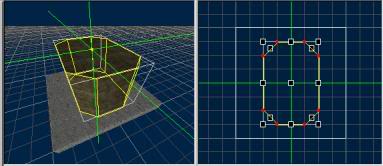
Go back to your map and move the marker in the Top view so that it’s one grid square south of the center of the column you created earlier, as in the image on the left.
If you were going to add a support to your column, this is probably where you’d want to add it.
Now, switch to the Front viewport. Zoom out a little so that you have some space to work and add a brush that is a triangular wedge with a thickness of 128 from the top of the column and looks similar to the figure below.
Look in the top view and see what’s been done. What you should see is that the brush lines up exactly with the green marker, and its thickness of 128 units extends along the front/back (X axis). The marker’s location in each view defines where the brush starts and the thickness you specify determines how far from the marker it extrudes.
By placing the marker carefully, you can lay brushes out exactly where you want them. Although this system of viewports and marker is somewhat different from many of the traditional editing tools, it’s also very powerful once you get used to it. Remember always to be aware of where the marker is and where you need it to be.
Adding Primitives
One last way of creating a new brush is to insert a primitive into the map. Primitives are pre-defined shapes that can be used instead of placing vertices. The main purpose of this is to quickly add brushes that would otherwise be very complex to build. You can add five shapes: Cubes, Cylinders, Pyramids, Spheres, or Domes.
To add a primitive, go to the Brush menu and choose Add Primitive . Select one of the primitive types. You’ll get a dialog that asks for a few options to set up the brush, and then the primitive appears at the marker. One difference between creating a brush this way and making it using Brush mode is that primitives come in un-textured. Be sure to apply the proper texture to your primitive once you’ve inserted it. To do so, select the new primitive and pressCTRL+T .
Note You may be tempted to fill your level with lots of domes and 20-sided columns, but be sure to read about optimizing performance in your levels before you do this. These objects can create great beauty where they’re used, but used in the wrong place they can create big problems with your level’s performance.
Selecting Brushes
To select a brush, left-click on it. In any of the viewports, move your mouse over the brush you want to select. If there are brushes stacked on top of each other, DEdit tries to pick the one it thinks you want. If a big brush is in front of a smaller brush, clicking inside the smaller one will select it even though the bigger one is “closer” to you. You can select brushes in order of their depth in the current viewport by pressing the T key when you click. In other words, if two identical brushes are stacked on top of each other in the current view, the T+lec-�click combination would select the one closest to the “front” of the view, and subsequent clicks would select the brushes behind that one.
One way of speeding up your work is to select multiple objects or brushes at once. The primary way to do this is using multi-select mode. In the Mode menu, select the Multiple Node Selection command. While you’re in this mode, selecting an object no longer de-selects the objects you have previously selected. With Multiple Node Selection chosen, when you select a new object it’s added to the selection. If you mistakenly add a brush to your selection, hold down the CTRL button and left-click on it again to remove it from the selection. It can be difficult sometimes to select the brush you want, and you can accidentally select the wrong brush. Pressing the U key de-selects all brushes, after which you can select the single brush you want to work with. Be sure to use the camera in Perspective view and press the U key frequently to be sure that you don’t grab the wrong brushes.
You can press and hold the CTRL button while clicking on brushes to add them to your selection. While the CTRL key is pressed, you can click any brush again to remove it from the selection.
Another way to select a group of brushes at once is by using a block selection, which can be used in any mode. Move the mouse into the top view, then left-click and drag out a rectangle that covers the pillar in the center of the level as well as the support you added before. You will see a white highlight that outlines the area you’re selecting. Once you release the mouse button, all the objects under the highlight are selected. In the case of brushes, a brush only becomes selected when the highlight touches one of its corners, so you can select a brush that’s on top of a larger brush without selecting the brush below it.
Lastly, you can use the Nodes tab in the Project window to select and find objects by name instead of having to find them visually. Click the Nodes tab to switch to it and examine what looks like a tree diagram of your whole level.
The list you see shows all of the brushes and objects in your level. Each of the names has a box and a symbol next to it. Move the camera in one of your views out so that you can see the whole level. Then, click on the box next to the object called “Brush1.” Two things happen. First, a check mark appears in the box and its name is highlighted. Second, one of the brushes (your pillar) is selected.
This way of selecting things is useful on larger levels, where you may know what brush you’d like to select, but can’t easily jump to it to select it. In that case, you can then use the Center View button (described earlier) to quickly center your views on the brush. You can do many other things
with the Nodes tab to organize your level as well. The Nodes tab is covered in greater detail later in this chapter.
The last major method for selecting brushes and other objects is via the Selection menu. The menu provides useful commands for working with several brushes at once, as well as a few commands for organizing your brushes.
The first two commands, All and None, are straightforward. Clicking None behaves exactly the same as pressing the U key: it clears all selections. If you choose All , then DEdit selects everything in the level: all objects and all brushes.
The Inverse command inverts the selection so that everything selected is unselected and vice versa.
The Container command tells DEdit to select an object’s parent object in the Nodes tree. You can use container objects to organize the objects in your maps without affecting the way the map works. You can read about using containers in the section on using and understanding nodes.
The Advanced command displays a dialog that will help you find objects and brushes based on their name or type. This is another feature designed to help you find objects in large levels where you may not be able to locate something right away visually, or to find large groups of objects quickly.
The Hide and Unhide Selected commands let you hide selected parts of the level from view if you’re not currently working on them. This will help your editor run a bit faster, and can help you to see parts of the level that would otherwise be hard to view with your camera. You can also use these commands to accomplish some complex tasks with carving and geometry mode (which you’ll learn about later). Since a hidden object isn’t affected by most actions while it’s hidden, hiding brushes can be used (like masking tape in painting) to protect certain brushes from work you’re doing on other nearby brushes. This is another command that you’ll read more about in the Nodes section.
The Hide Inverse and Unhide Inverse commands are just like the above commands, but they operate on anything that you have not selected. They are commonly used for hiding items other than the ones you’re currently working on. For example, in cases where you’re working on only a small area of a large level, you can speed things up by hiding the rest of the level. It can also be useful to hide other brushes when you need to do work on the geometry of a brush that’s too tightly packed in among others to easily find its vertices.
The Mirror command allows you to flip a shape or group of objects in a level. You can use the mirroring commands on any brush, object, or group of brushes and objects. We’ll discuss the Mirror command later.
The Save as Prefab command takes the currently selected objects and brushes and stores them as a Prefab in their own file so that you can use them in other levels, or in other places in the current levels. Once you’ve saved a Prefab into its own file, you can then import the prefab again using the File menu Import World command. Prefabs can be as simple as a vending machine or as complex as an entire room complete with lights and characters.
The Generate Unique Names command creates a unique name for objects that have identical names. In cases such as AI paths and scripting, this can be important, since some objects use the names of other objects to select them as a target, to move them, or to send them messages. Unless you’re working on such tasks, you shouldn’t have to use this command.
The Group Selection command (related to the Container command) adds a new container object and groups the selected objects together in it. This command is very helpful for sorting large levels or rooms into smaller parts. See the Nodes section of this document to learn more about containers and their use.
Manipulating Brushes
In addition to the grab handle at the center of each brush, there are several other ways to rearrange your brushes in the editor. Use the M key to move selected objects, including brushes. Press and hold the M key, and then click and drag with the mouse to move the objects wherever you drag them.
You can also rotate your brushes, which is very useful when building symmetrical areas. As an example, assume you want to make a second copy of your pillar and its support but facing the opposite way. The slow way would be to lay out each brush again by hand, which would be tedious. The faster way would be to copy the current brush, then just rotate it into the new position.
Switch to multi-select mode (using either the toolbar buttons or Mode menu Multiple Node Selection command. Select the pillar brush, and then select the support brush. Once you have them both selected, press CTRL+C to copy them. Since you don’t want to insert the brushes at the green marker when you paste them, from the Edit menu use the Alternate Paste command.
When you perform an Alternate Paste, DEdit pastes the object into the current world at the coordinates where it was copied out instead of at the marker. This is most useful in two cases. First, when you want to rotate or realign the brush slightly in relation to the original. Second, in cases where the new brush will be in a new world, but be in the same exact position there as the old brush was in the old world. For example, you might want to copy or paste parts of your world into a test world, just to try a few ideas without modifying the original world’s design. You would not want to align rooms, lights, and so on by adjusting the green marker for each paste operation.
Press CTRL+ALT+V to paste in the new brush. The selection will flicker, but since you pasted into exactly the same place that you cut from, nothing will appear to change. Next, go into the top view and move the marker so that it’s right at the tip of the support brush:
Right-click in the top view and select Rotate Selection . Since we want to make an archway out of the two pillars, enter 180 in the Degrees box that appears. When you click OK , you’ll see your selection move. If you use the camera in the Perspective viewport to look at what’s happened, you’ll see that there’s now a mirror image of the pillar on the opposite side of the original. Notice that the marker defines the center around which the brush is rotated.
Note: You can also hold down the N key to rotate the selected objects, but since this rotates the brush in very small increments you must be careful to rotate neatly. It’s difficult to rotate an object by exactly 90 degrees by hand; using the menu command is generally faster and more accurate. Additionally, you can hold down SHIFT+N to rotate in 15-degree increments. The most important thing to remember about rotations is that if your rotation operation leaves brush vertices off the grid, then precision errors can occur during processing.
Another way to flip objects is to use Mirror commands in the Selection menu. This method works well for brushes that are not symmetrical enough to rotate, such as a brush that’s beveled on one edge in order to meet up neatly at a corner. Each command flips the brush along a different axis relative to the world. It doesn’t matter which viewport you use the mirroring commands in, since the flip axis is relative to the world, not the viewport. A top/bottom mirror inverts the brush along its Y-axis, a front/back mirror along the X-axis, and so on.
Resizing a brush (which you’ll want to do now, since your level’s floor is too small) is done using the drag handles on the edges and corners of a brush. Press the U key to unselect everything, then select the brush that makes the floor of your level. You will see filled boxes appear at each corner and on each edge that look just like the one in the middle for moving the brush. The ones on the edges are for stretching the brush in the direction of that axis. The handles on the corners allow for resizing in both directions at once.
Go to the top view and resize your floor brush with the drag handles until it is four times its current size on each of the edges and it is underneath both of your pillars so that players can walk underneath them. You should get something like the picture below. It may also be useful to make the grid size larger (128 or 256) to simplify resizing the brush properly.
Having the two types of drag handles helps when you want to either quickly resize a brush in multiple dimensions like your floor (corner) or resize it in only one direction as you’d do if you extended a hallway (edge). These handles appear around any group of things in the world, including objects. You can use the drag handles to widen a circle of lights or spread out a group of start points as well as using it to increase the size of a brush. You can even mirror a brush by dragging it inside out. DEdit is smart enough to flip the face normals of the brush so that they still end up pointing outward as they should.
However, one thing that can happen when resizing a group of brushes is that you can re-shape some of the brushes in ways that you didn’t intend. For example, select both the floor brush and the right hand pillar in your level. Drag the right edge resize handle to the right by one square. What you should see is that not only does the pillar grow, it also moves to the right. This is because DEdit treats the entire group selection as one scalable object/brush.
That sort of movement, if you’re not aware of it, can cause leaks when you use the handles to resize a hallway whose floors and ceilings aren’t all the same length. For the same reason, you don’t want to use these handles to move a pair of walls to narrow a hallway. The walls thicken or shrink as they’re moved, and not usually by nice, neat increments. A pair of walls that began as 32 units thick each and 128 units apart might end up 196 units apart as you intend, but be 45 units thick each. That’s not a unit that will be easy to fit textures to or align with your other walls and floors. Conversely, if you scale a lamp post that has a lens flare sprite attached at just the right location, resizing the lamp post and the sprite as a group will ensure that the sprite stays as the proper location.
This brings up the last possible problem with resizing objects. If a brush has vertices that fall on points that wouldn’t line up with even a 1x1 grid spacing (the smallest DEdit and LithTech can handle without possibly producing precision errors; see the section of this chapter on problem brushes), the Processor may have some trouble getting the corners of the brush’s faces to line up when the level is processed. This can cause gaps to appear between faces and may also cause level leaks.
Note: You should undo your resize by hitting CTRL+Z in order to return your column to its proper size now.
If you do use the drag handles to resize an object, make sure you verify that all of the moved vertices wind up on the grid. If you can’t, be sure to correct the error by shifting vertices back onto the grid in Geometry Mode as described in the following section on brush manipulation power tools.