EDIT: 04/29/2021 JKHub has been taken down due to a fire in their datacenter. I've reuploaded JkEdit here
JkEdit 3.24 file - Star Wars Jedi Knight: Dark Forces II - Mod DB
EDIT: 1/21/2022 I've uploaded a tutorial on how to get JkEdit to run if you're using the Steam or GOG port
How to run JkEdit on the Steam/GOG version
I've also added an FAQ to the bottom of this tutorial as I recently discovered it via an archive on MagicForce's website and it contains some invaluable information.
JKedit was produced by Ole Thomason. It was produced through his company called Magicforce. There used to be tutorials on how to use the program available on it, however this information was removed in the mid 2000s. To make this even worse, the website disallowed archive.org caching.
However these tutorials were archived and are now available here for everyone. Unfortunately some of the images are lost. However most of the important articles have their images.
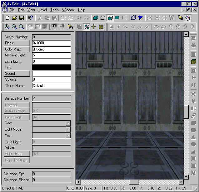
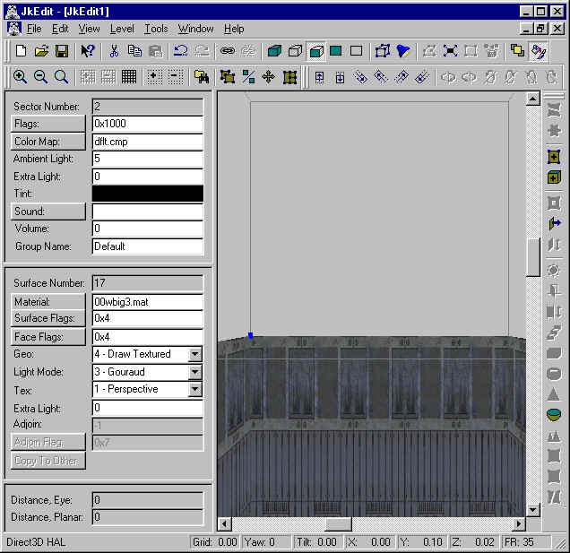
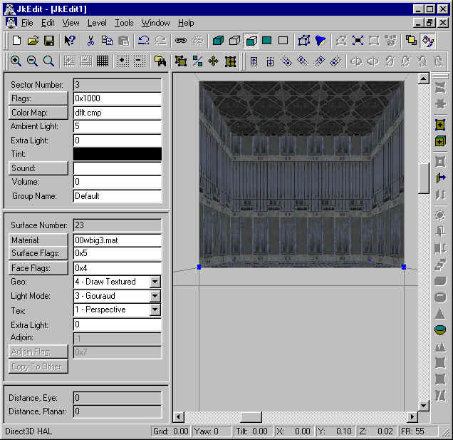
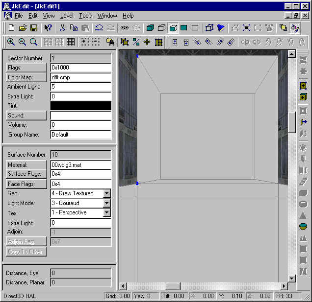
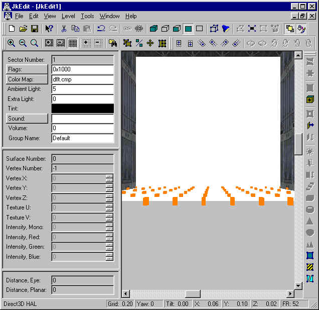
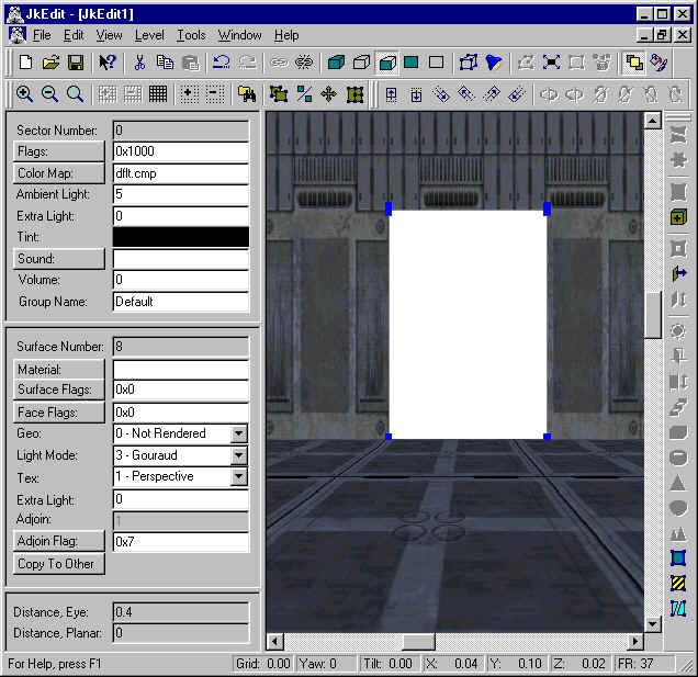
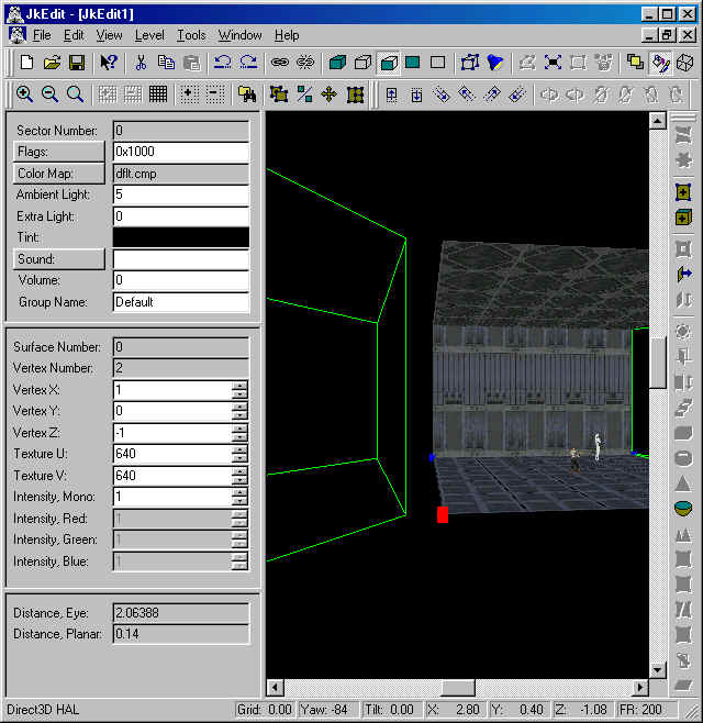
Lesson 1: The Basics
Listed below are definitions for many of the terms you'll find in JKEdit.
Vertices:
Vertices are points in space. They are represented by small dots in JKEdit
Surfaces:
A surface is a minimum of 3 vertices on a plane. An ordinary wall will have a minimum of four vertices, one in each corner.
Sectors:
A basic sector is a set of surfaces like a room, a hallway or an outdoor area. One level is made up of many sectors.
Linking:
Vertices may be linked together (at a corner) in order to reduce the amount of vertices in a sector.
Texture:
A default texture is assigned to each surface when it's created. Textures in Jedi Knight are stored in files with the extension of .mat.
3do:
3do is a term for 3-D objects. These include Kyle, weapons, Storm Troopers and other enemies. Other 3-D objects includes tables, chairs, elevators, catwalks, decorative objects, etc.
Sprites:
Sprites are 2-D objects such as sparks, particle streams, smoke and fire.
Cogs:
Cog is a file extension for a script file. These files control the action of doors, weapons, force powers and multi-player scoring.
Surface Flags:
Surface flags are used to describe or indicate what properties a surface will have. One surface in a sector could have the surface flag of 'dirt floor' or 'steel floor' and another might have the surface flag of 'shallow water' or 'impassable'.
Sector Flags:
Sector flags are used to indicate what properties you would like to attribute to an entire sector such as: 'no gravity', 'under water', 'contains collide box' or 'hide on map'.
Lighting:
Lighting indicates the source, the direction and intensity of the light. Light may be attached to a vertex or an entire sector.
Adjoining:
This means connecting two identical back-to-back surfaces together. Typically adjoined surfaces appears as being transparent.
Rules Regarding Sectors:
Every surface and each sector must be convex.
For a surface, convex means that no angle between two neighboring edges is greater than 180°. This is also true for sectors. Two neighboring surfaces must not have an angle greater than 180°.
A sector must be totally closed by its surfaces, including any adjoined, transparent surfaces.
Lesson 2 - Splitting a surface and creation of a Hallway
In this tutorial you will learn how to create a hallway. This involves learning how to split a surface into smaller pieces and how to use the Extrude funtion to make the actual hallway.
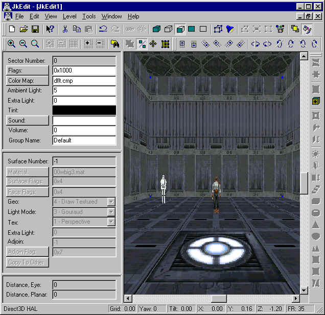
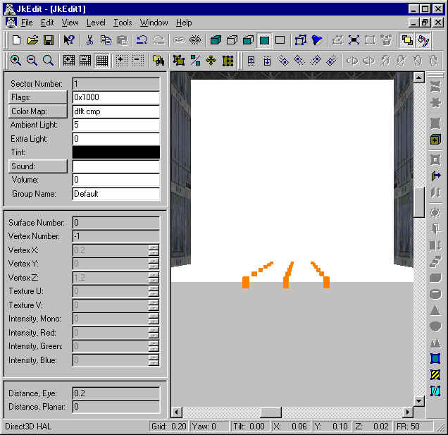
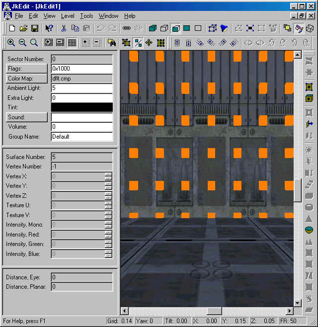
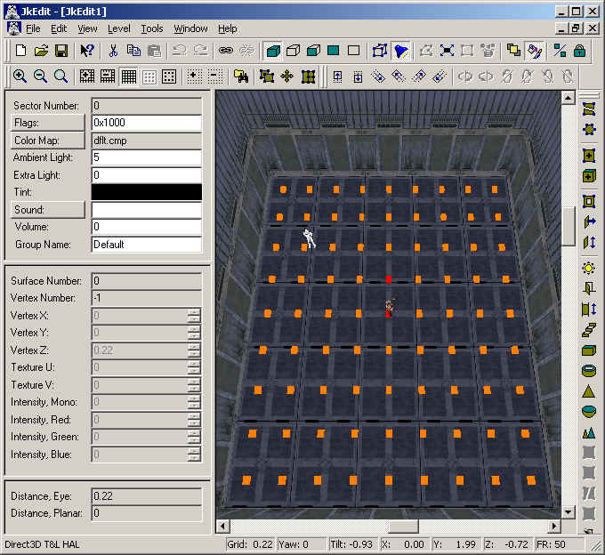
We will start making a new file, so we begin with selecting New in the File menu. This will give us a new level consisting of one sector:
You can use the arrow keys on your keyboard to move around, but for now we just want to take a closer look at the surface infront of us. Let's click on it with the mouse:
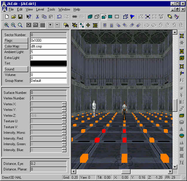
Now, that unlocked all kinds of neat things in the toolbars, but for now we will only concentrate on a few options. Try to click on the button with the grid (Grid On):
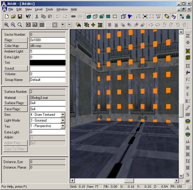
A node grid has been attached to the surface. By using the plus and minus button on the toolbar, we can adjust the grid setting, which by the way, you can see the value of in the status bar. For now, leave the grid at 0.20. We will now split the surface.
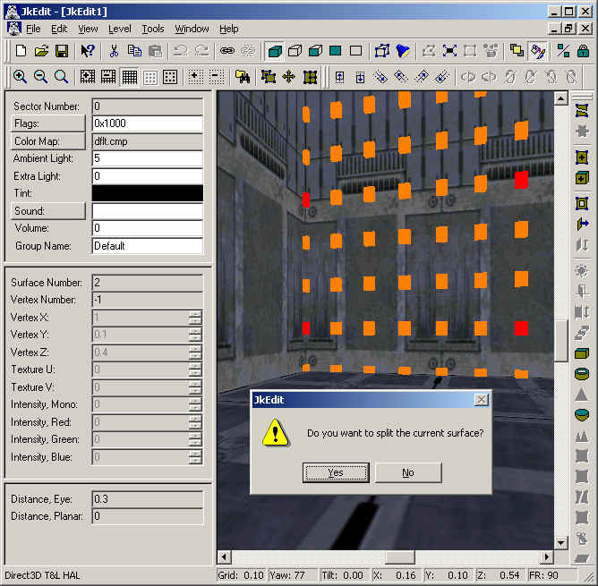
Now we are able to do our first surface split. Note that the Split Sector/Surface button is enabled in the toolbar. Click on the button and say yes in the warning dialog. The surface split will take place, and we note that the left surface remains selected:
Click on the right part and use the mouse to select two new grid nodes:
Again we are able to split the surface using the Split Sector/Surface button in the toolbar. Doing so, we end up with three surfaces, now the middle being selected.
We select two new grid nodes:
After splitting the surface and selecting the new lower surface, we unselect the grid by clicking on the grid node button in the toolbar. We should now have the lower and middle surface selected:
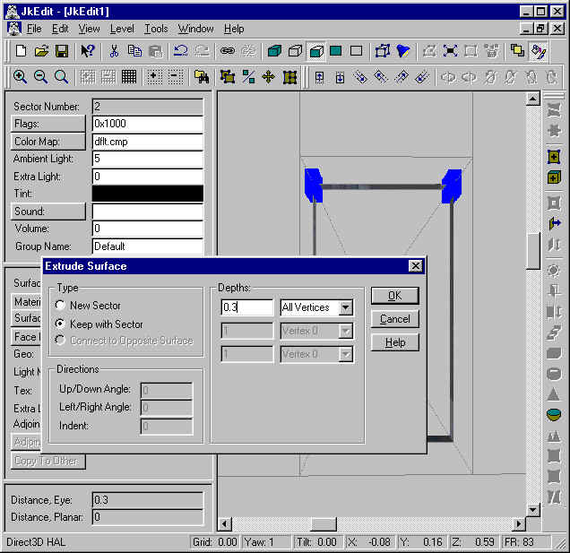
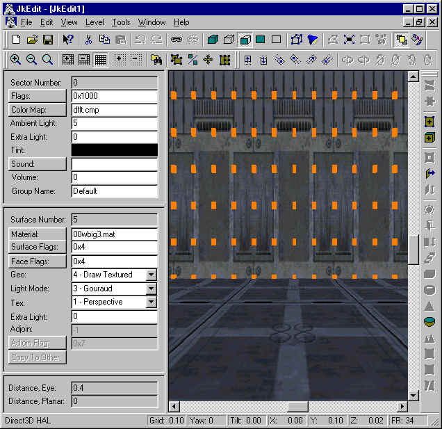
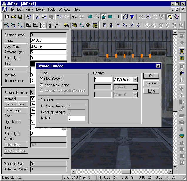
At this moment we have finished all our surface splitting. We can now proceed to create the actual hallway. Making sure the lower middle surface is selected, we click on the Extrude Surface button in the toolbar. Leaving the depth value in the Extrude Surface dialog to 1.0, we end up with this:
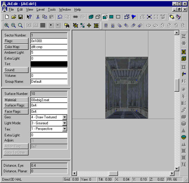
This is the hallway and it is also a new sector.
You can now play with the rendering modes button on the toolbar to have both sectors rendered. And you can also use the Test Level command in the Tools menu to have your new level tested in the Jedi Knight game engine.
You have now learned to split a surface into smaller pieces. You have learned to use the Extrude Surface function to create new sectors. In Lesson 3 we will show you how to split sectors, and discuss what that can be used for.
Lesson 3 - Splitting a sector
In this tutorial you will learn how to split a sector. This is very important because this allows you to create very cool 3D geometry architectures.
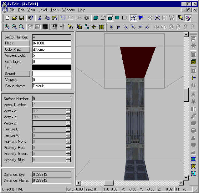
We will start making a new file, so we begin with selecting New in the File menu. This will give us a new level consisting of one sector:
You can use the arrow keys on your keyboard to move around in order to be in a position like this:
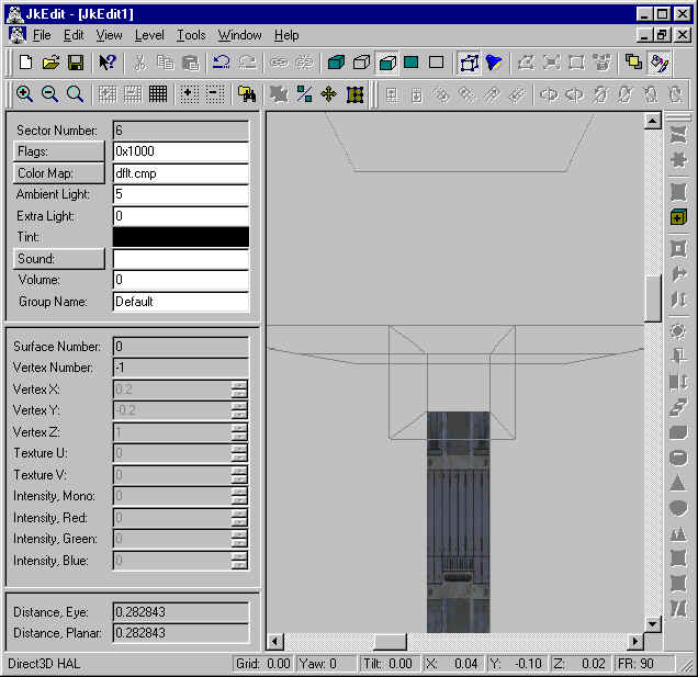
Now we select Sector Mode by clicking on the Sector Mode button in the toolbar. Having done that, we enter split mode by clicking on the Grid On button in the toolbar. You will end up with a view like this:
A node grid has been attached to the sector. By using the plus and minus button on the toolbar, we can adjust the grid setting, which by the way, you can see the value of in the status bar. For now, leave the grid at 0.20. We will now split the sector. Select three nodes on the grid as indicated below by using click with the mouse:
Now we are able to do our first sector split. Note that the Split Sector/Surface button is enabled in the toolbar. Click on the button and say yes in the warning dialog. The sector split will take place, and we note that the current sector remains selected:
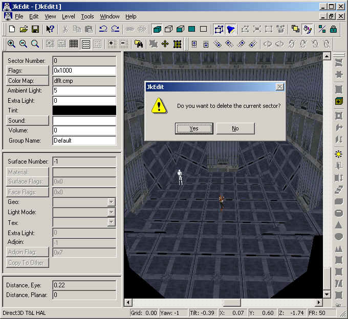
Click on the corner sector part and select Delete in the Edit menu. Answer yes in the warning dialog. After reselecting the front sector, you should have a view like this:
Now we finish Sector Mode by clicking on the Sector Mode button in the toolbar. Note that the texture of the corner surface is not exactly what we had in mind. But we can easily fix that. Select the surface to the left of the corner surface. Select Copy in the Edit menu (or use C). This will copy the texture (or material) to the clipboard. Click on the corner surface and select Paste in the Edit menu (or use V). This will paste the clipboard contents to the corner surface:
You can now play with the rendering modes button on the toolbar to see the final result. And you can also use the Test Level command in the Tools menu to have your new level tested in the Jedi Knight game engine.
You have now learned to split a sector and to use copy and paste to align textures.
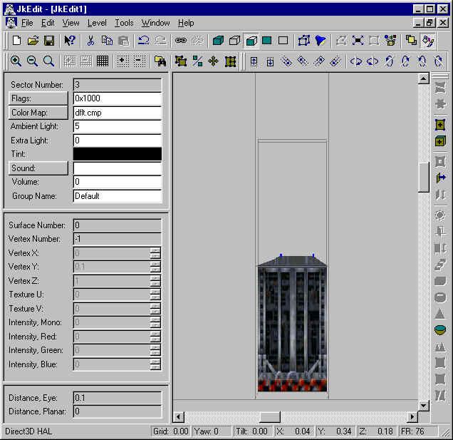
Lesson 4 - Create a door, manually
In this tutorial you will learn how to create a simple door using JkEdit.
You create a door by inserting a suitable 3DO object into your level. Make sure no surfaces or vertices are selected. Now you can select Insert in the Edit menu (or just press the Ins key). In the Add Template to Level dialog look for a door object, e.g. 3x3door_1. Select the door object , and click Ok.
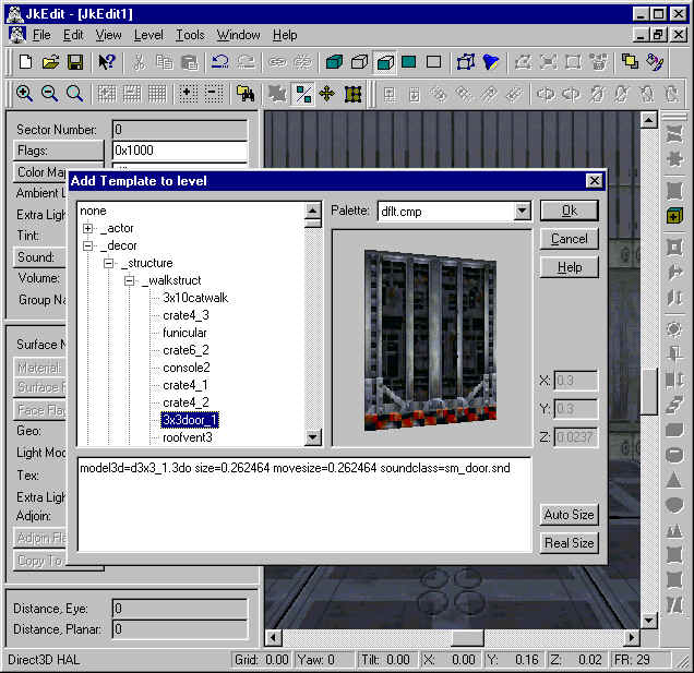
At this moment you should see the newly inserted door object in your level. Assuming you picked the 3x3door_1 object, you will now have to create a suitable set of sectors for the door object and for connecting hallways, matching the height, width, and depth of the door. In this case the door is 0.3 x 0.3 x 0.0237 units (as seen in the Add Template to Level dialog).
You will have to create the two hallway sectors of 0.3 x 0.3 and the door sector of 0.3 x 0.3 x 0.0237 units and place the door object into this. We place the door sector between two existing hallway sectors of the same width and height.
We create the first hallway sector using the Split Surface and Extrude Surface command, as described in tutorial 2. By setting the grid size to 0.1 we create a 0.3 x 0.3 x 0.1 sector:

At the end surface of this new sector, we create the door sector with a depth of 0.0237. Select the end surface, and use the Extrude Surface command:
We now create the second hallway sector at the end of the door sector. Select the new end surface, and use the Extrude command with a depth of 1.0:
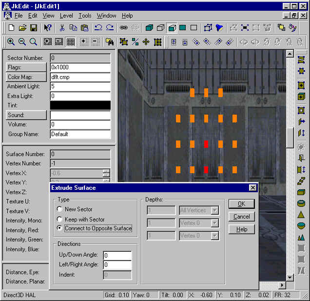
We have now created two hallway sectors and a door sector between the two. It is necessary to enlarge the door sector to allow for room for the door when it opens. In this tutorial we assume the door is opening upwards. We use the Extrude Surface function to extrude the top surface of the door sector with a depth of 0.3, but specifying Keep with Sector:
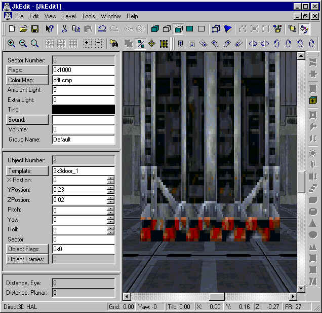
Now we move the door object into the door sector. Select the door object, and use the toolbar move buttons. You can fine adjust by holding down the key when you move the door object.
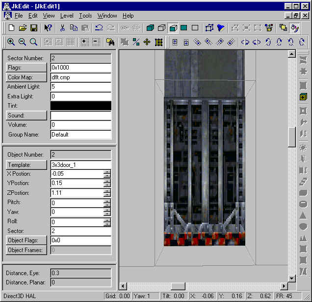
In the Object Properties panel change the Object Flags of the door to 0x448. In the same panel, click on Object Frames. In this dialog, create two frames and specify Center for Frame 1 and Top for Frame2. These two frames will now denote the start and end position of the door.
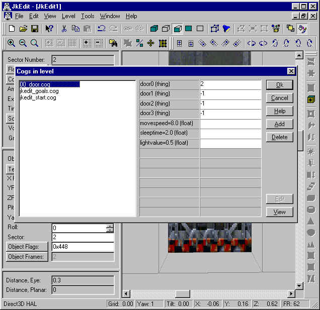
You will now have to add a door cog script to your level, using the Cogs in Level dialog. On this dialog, use the Add button to add the script 00_door.cog to your level. In the Cogs In Level dialog, click on View. You will notice that this cog script takes 7 parameters (4 doors ID, moveSpeed, sleepTime, lightValue), where the last 3 parameters have defaults. Assuming the Object Number of your door object in the Object Property panel is 2, type the following 4 parameters in the Cogs In Level dialog: 2 –1 –1 –1.
You have now created your door.
Lesson 5 - Create an elevator, manually
In this tutorial you will learn how to create a simple elevator.
You create a simple elevator by inserting a suitable 3DO object into your level. Make sure no surfaces or vertices are selected. Now you can select Insert in the Edit menu (or just press the Ins key). In the Add Templates to Level dialog look for an elevator object, e.g. 2x2elev. Select the elevator object, and click Ok.
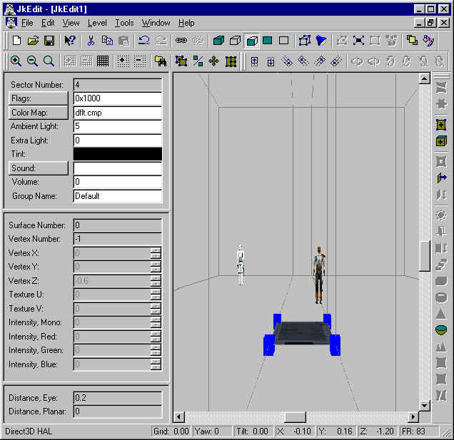
At this moment you should see the newly inserted elevator object in your level. Assuming you picked the 2x2elev object, you will now have to create a set of suitable elevator shafts for the elevator object, matching the dimensions of the elevator. In this case the elevator is 0.196 x 0.196 x 0.0621 units. You will have to create an elevator shaft of 0.2 x 0.2 units.
We do this by attaching a 0.2 grid to the floor surface. On this grid we select 4 grid nodes in sequential order:
First we create the elevator shaft in the current sector. We do this having the four grid nodes selected. We can now select the Carve Sector/Surface command specifying NO catwalk:
By clicking OK in the Carve Sector/Surface dialog, we have the first elevator shaft created:
You create the second elevator shaft by using the Extrude Surface command (depth 1.0) on the new elevator bottom surface:
Having created the elevator shaft, move the elevator object so it fit inside the top of the second elevator shaft. In the Object Properties panel change the Object Flags to 0x448. In the same panel, click on Object Frames. In this dialog, add two frames and specify Center for Frame 1 and for Frame2. Now reduce the Y parameter of Frame 2 with the height of the elevator shaft (1.0). These two frames will now denote the top and bottom position of the elevator.
You will now have to add an elevator cog script to your level, using the Cogs in Level dialog. On this dialog, use the Add button to add the script 00_std_elev.cog to your level. In the Cogs In Level dialog, click on View.
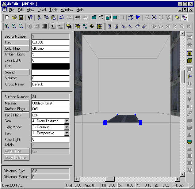
You will notice that this cog script takes 6 parameters (2 surfaces ID, start_wait, sleepTime, speed), where the last 3 parameters have defaults. To get the surface ID’s, we select Transparent for the Adjoin Rendering parameter in the Options dialog. This enables us to select the (invisible) surfaces around the elevator in the upper elevator shaft. Assuming the Object Number of your elevator object in the Object Property panel is 2 and the Surface Number of two of the top surfaces of the elevator shaft is 24 and 31, type the following 3 parameters in the Cogs In Level dialog: 24 31 2.
You have now created your elevator. If you like, you can add one more 00_std_elev.cog to your level specifying the other two (invisible) surfaces as the first two parameters and the elevator object as the third parameter.
When you test the elevator, you will notice that the elevator object disappears when reaching the bottom. You can easily fix this by creating a sub-shaft sector at the bottom of the second elevator shaft. Use the Extrude Surface command for that, specifying a depth of 0.0621 (the height of the elevator object).
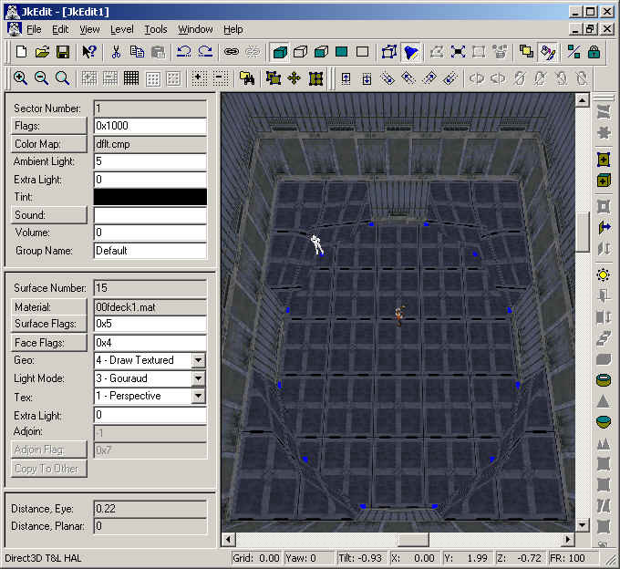
Lesson 6 - Creating breaking glass, manually
In this tutorial you will learn how to create breaking glass using JkEdit.
You create a glass surface by modifying the adjoin surface between two sectors. First we will create a new level, and extrude a surface:
Now we change the Adjoin Rendering to Solid by clicking on the Adjoin Rendering button in the toolbar. By clicking on the window sector, we can now select the adjoined surface:
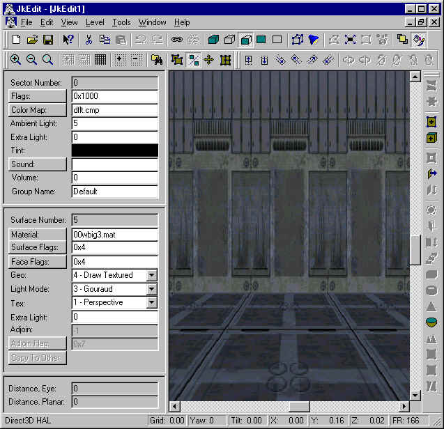
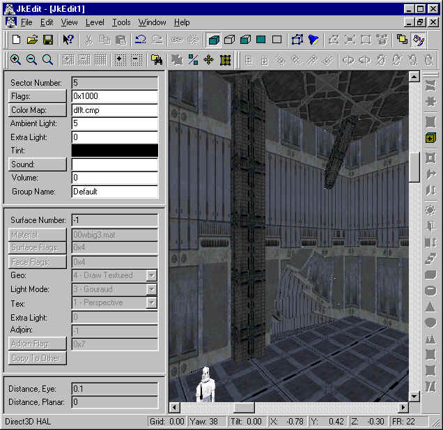
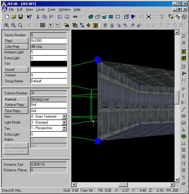
We select the material 00wglas1.mat for the adjoined surface, and we change the surface parameters Surface Flags to 0x6, Face Flags to 0x2 (to be able to see through the surface), Geo to 4 - Draw textured, Light to 3 - Gouraud, and Tex to 1 - Perspective. We also change the Adjoin Flag to 0x5 (to avoid being able to pass through the surface). Having done this, we repeat these parameters for the other adjoined surface by clicking on the Copy To Other button in the Surface panel.
In order to make the glass breakable we will have to add a suitable cog to our level. In the Cogs In Level dialog, we add 00_breakingglass.cog to our level. By clicking on the View button, we notice that this cog takes two required parameters. These parameters are the two adjoined surfaces in question, #8 and #9:
We have now created our breaking glass window.
Lesson 7 - Create force fields, manually
In this tutorial you will learn how to create force fields using JkEdit.
You create a force field by modifying the adjoin surface between two sectors. First we will create a new level, and extrude a surface:
Now we change the Adjoin Rendering to Solid by clicking on the Adjoin Rendering button in the toolbar. By clicking on the force field sector, we can now select the adjoined surface:
We select the material 00wwarny.mat for the adjoined surface, and we change the surface parameters Surface Flags to 0x6, Face Flags to 0x2 (to be able to see through the surface), Geo to 4 - Draw Textured, Light to 3 - Gouraud, and Tex to 1 - Perspective. We also change the Adjoin Flag to 0x5 (to avoid being able to pass through the surface). Having done this, we repeat these parameters for the other adjoined surface by clicking on the Copy To Other button in the Surface panel.
In order to turn the force field on and off, we create a switch sector left to the extruded sector:
In order to make the force field we will have to add a suitable cog to our level. We will have to extract a cog from JKL.GOB in the Jedi Knight resource directory. We select 10_ffieldswitch.cog, and use the Save As button to save this file into our JkEdit directory:
We then load it into our level using the Files in Level command. In the Cogs In Level dialog, we add 10_ffieldswitch.cog to our level. By clicking on the View button, we notice that this cog takes three required parameters. These parameters are a switch surface and two adjoined surfaces. Using the Adjoin Rendering button in the toolbar, we notice that the switch surface is 20, and the two adjoinded surfaces is 8 and 9. We enter these parameters into the Cogs In Level dialog:
We have now created our force field.
If you like, you could add another switch sector inside the original extruded sector. Add another 10_ffieldswitch.cog to your level, with appropriate parameters for the switch and the adjoined surfaces. Then you can operate activation/deactivation of the force field from both sides.
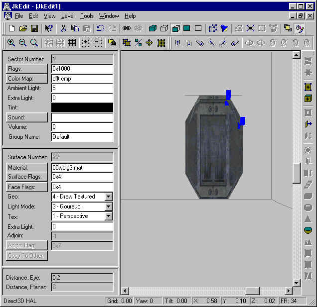
Lesson 8 - Create advanced geometry, I
In this tutorial you will learn how to create advanced geometry in your level using JkEdit.
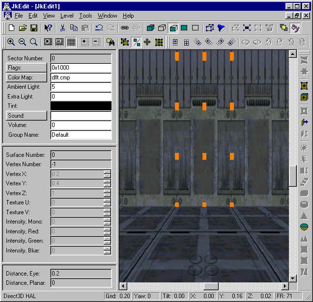
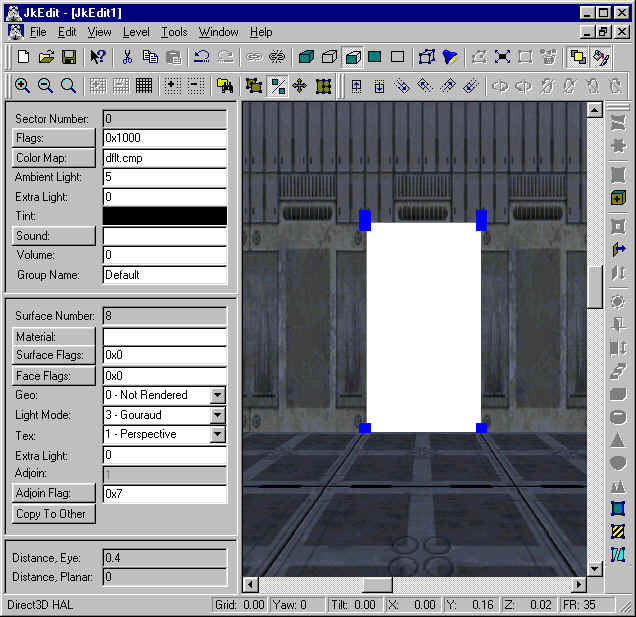
For this we will use the new Split, Extrude and Expand features to create a new main sector connected to the original sector through arch openings. First we will create a new level, and attach a node grid to the surface in front:
By using the plus and minus button in the toolbar, we make sure the grid spacing is 0.10, which can be seen in the status bar. Moving a little bit to the right, we select a node on the node grid:

By pressing down the key, we select the second node on the grid:

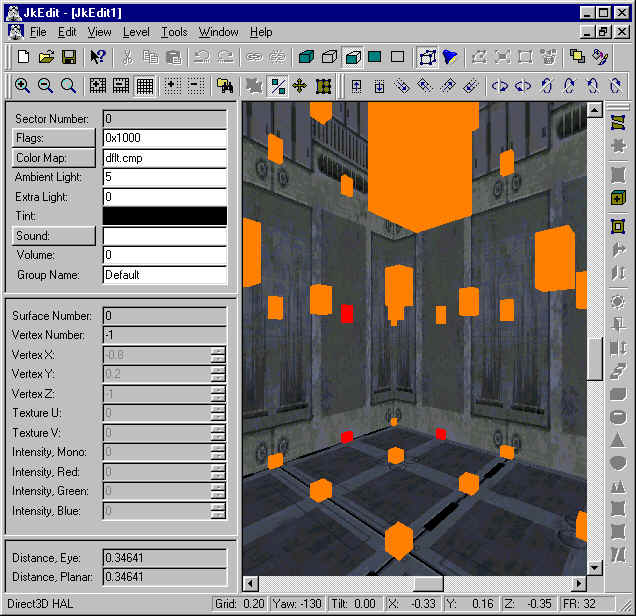
Keeping on pressing down the key, we select 6 more nodes on the grid in the same order:
We are now ready to split the surface. Select Split Sector/Surface in the Tools menu, and click Yes in the dialog:

In order to Extrude, click on the middle surface and select the Extrude dialog in the Tools menu. Specify a depth of 0.1 and click OK in the Extrude dialog:
We are now ready to create the second main sector. Select the end surface in the arch opening and attach a node grid to it. Select two nodes on the grid, bottom one first and the second one by using click. Select Expand in the Tools menu and specify the following parameters:
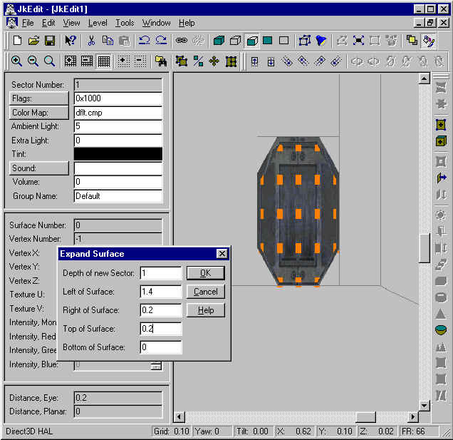
Click on OK in the Expand dialog to create the new sector::
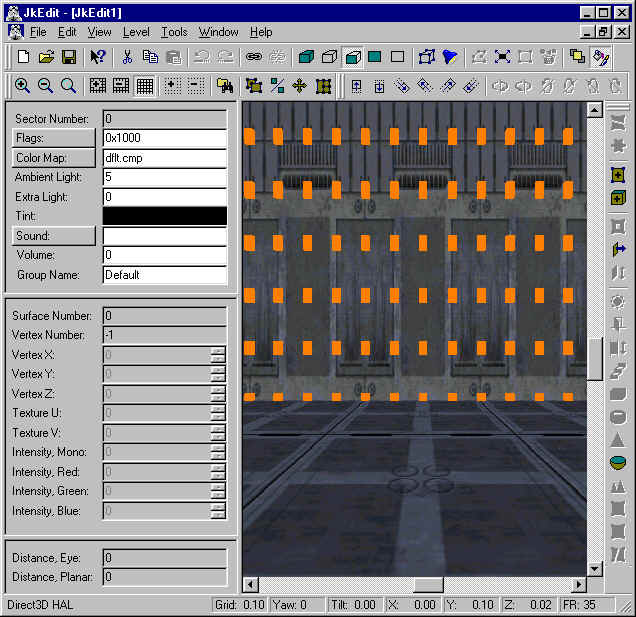
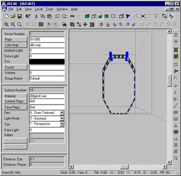
If you like, you can select one of the surfaces in the arch opening and change the material to e.g. 00light4.mat, and use copy/paste to set this material up for all the surfaces in the arch opening. Use the Texture Coordinate dialog to adjust the texture coordinates (set Start Vertex to 0).
Click on the front wall surface and scroll left until we see the stormtrooper in front of us. Since he is in the way for our needs right now, we click on the Object Rendering button in the toolbar. This removes 3DO objects. We are now ready to create our second arch opening, starting with attaching a node grid to the surface and selecting 8 nodes as before, followed with splitting the surface:
On the node grid, we select two nodes, the bottom one first and the second one by using click. Select Extrude in the Tools menu and specify the following parameters:
Click OK in the Extrude Surface dialog, and we will now see a perfect connected arch to our already created second main sector:
Again we alter the surface material of the new arch surfaces:
We have now finished creating our new main sector connected through arch ways to our original main sector. You should now have a basic idea about how the powerfull Split, Extrude, and Expand functions in JkEdit can be used to create fast advanced level geometry.
You have hopefully noticed the clever usage of specifying the up vector required for indicating the priority direction for the multiple surface splitting.
Lesson 9 - Create water, manually
In this tutorial you will learn how to create water using JkEdit.
You create water by modifying the adjoin surface between two sectors. First we will create a new level, and extrude a surface in the floor:
For fun, we select the material 00_grey1.mat for the side and bottom surfaces in the water sector. By using Copy and Paste, we can align the surface textures in the new surface:
Now we change the Adjoin Rendering to Solid by clicking on the Adjoin Rendering button in the toolbar. By clicking on the water sector, we can now select the adjoined surface:
We select the material 00fwater.mat for the adjoined surface, and we change the surface parameters Surface Flags to 0x20006, Face Flags to 0x2 (to be able to see through the surface), Geo to 4 - Draw Textured, Light to 3 - Gouraud, and Tex to 1 - Perspective. Having done this, we repeat these parameters for the other adjoined surface by clicking on the Copy To Other button in the Surface panel.
Now we select the water sector by scrolling down and click on a surface. Change the Sector Flags to 0x1006, and add 00underwater.wav with a Volume of 3 as water sound to our water sector:
In order to create water motion we will have to add a suitable cog to our level. In the Cogs In Level dialog, we add 00_conveyor.cog to our level. By clicking on the View button, we notice that this cog takes ten required parameters.
The first parameter is a vector of the form (x/z/y) and denotes the direction of the motion. Note the order of x, z, and y. We set this vector to (-1.0/0.0/0.0). The second parameter is the motion speed. We set this 0.5. The remaining eight parameters are surfaces to be given the motion. We set the first one to 8, and the rest to -1:
We have now created our water.
Lesson 10 - Create a catwalk, manually
In this tutorial you will learn how to create a catwalk using JkEdit.
You create a catwalk by using a combination of Extrude Surface, Split Sector/Surface, and Link/Unlink Surface. First we will create a new level, and extrude the end surface in order to make a new sector:
In this new sector 1, we select the floor surface and extrude in order to make a pit:
Now we select the end surface in sector 1, and use the extrude function to create one more sector:
We are now ready to create the catwalk so that we can walk between sector 0 and sector 3. The catwalk will be placed at the top of sector 2. We create the top surface of the catwalk by splitting the floor surface in sector 1. Click on a side surface in sector 1:
Now select the Sector Rendered button in the toolbar, and click on the Adjoin Rendering button in the toolbar. Select the floor surface and attach a node grid to it:
We now uses the Split Sector/Surface command to split the floor surface twice:
On the middle surface #24, we now uses the Unlink command to remove the adjoin relationship. We returns to Sector Rendering & Wireframes, unselect the Adjoin Rendering, and uses copy and paste to setup a suitable texture for the catwalk surface:
In order to create the side surfaces of the catwalk, we will split sector 2 twice vertically:
In this new middle pit sector, we do one more sector split horizontally in order to create the bottom of the catwalk:
By moving into the catwalk sector, we now select each of the surfaces and used the Unlink command to remove the adjoin relationships.
Having done this, we can use the Error dialog to notice, that sector 4 is no longer connected to other sectors. We can thus delete the sector by entering Sector mode and press delete:.
What we have left to do, is to use copy and paste to attach proper textures to our catwalk:
Lesson 11 - Create a door, automatic
In this tutorial you will learn how to create a door using the Create Door command in JkEdit.
First we will create a new level, and attach a node grid to the surface in front:

On this node grid we will have to select two nodes. The bottom node indicates the bottom middle of the door, and the second node together with the first indicates the up direction (up vector) for the door:
Now we bring up the Create Door dialog by clicking on the Create Door button in the toolbar. We select the door 3x3door_1 and change the Back Depth to 1:
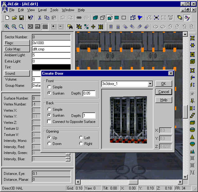
Now click OK in the dialog, and the door will be created with the necessary sectors surrounding it:
You have now created our door.
Lesson 12 - Create an elevator, automatic
In this tutorial you will learn how to create an elevator using the Create Elevator command in JkEdit.
First we will create a new level, and attach a node grid to the floor surface:
On this node grid we will have to select two nodes. The first node indicates the middle of the elevator, and the second node together with the first indicates the up direction (up vector) for the elevator:
Now we bring up the Create Elevator dialog by clicking on the Create Elevator button in the toolbar. We select the elevator 2x2elev and leave the remaining parameters:
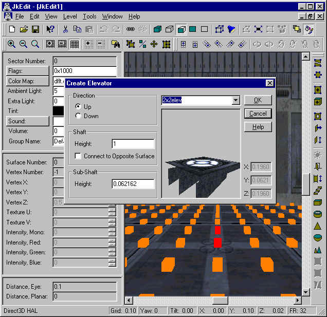
Now click OK in the dialog, and the elevator will be created with the necessary sectors surrounding it:
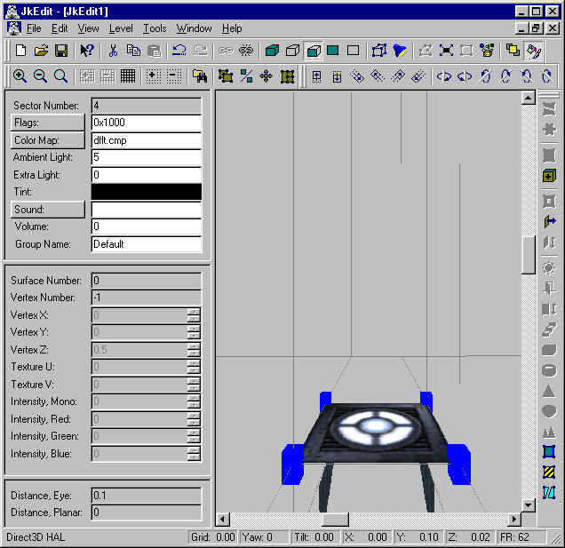
You have now created our elevator.
Lesson 13 - Create advanced geometry, II
In this tutorial you will learn how to create advanced geometry in your level using JkEdit.
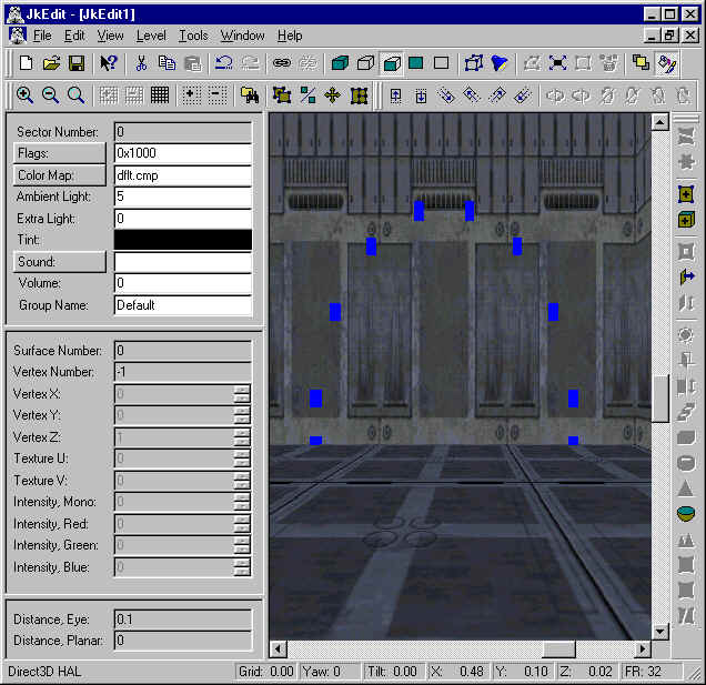
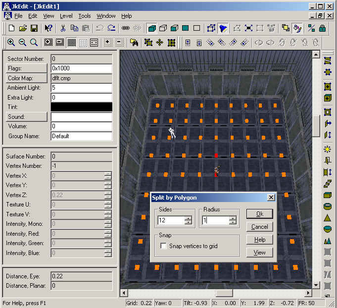
For this we will use the new Split by Polygon, Extrude and Carve commands. First we will create a new level, and attach a node grid to the surface in front:
By using the plus and minus button in the toolbar, we make sure the grid spacing is 0.10, which can be seen in the status bar. Moving a little bit to the right, we select two nodes on the node grid, the bottom one first. In the Tools menu, we select the Split by Polygon command:
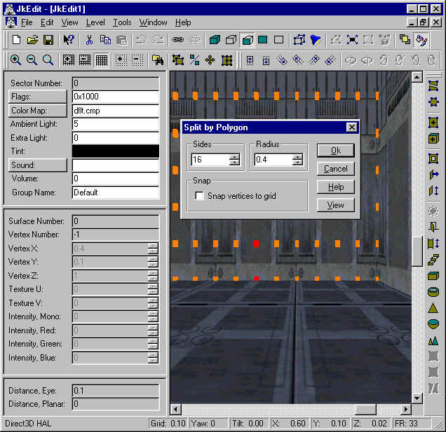
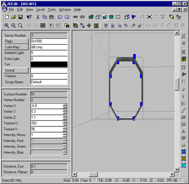
In the Split by Polygon dialog we change the number of sides to 16 and the radius to 0.4. Now click on the View button to see the specifed result:
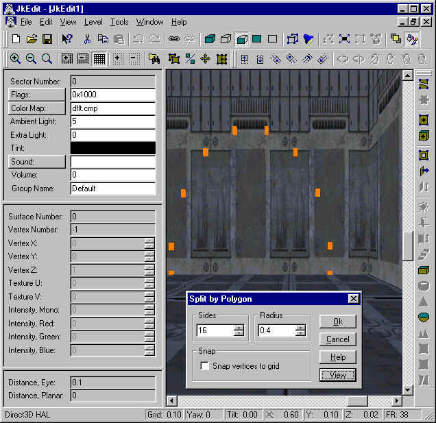
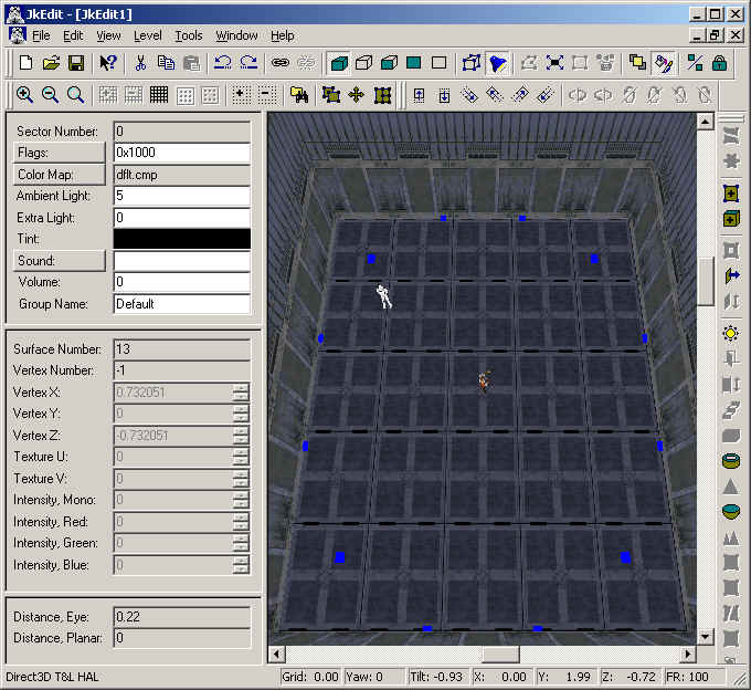
By clicking Ok, we accepth splitting the surface and thus obtain a half circle surface:
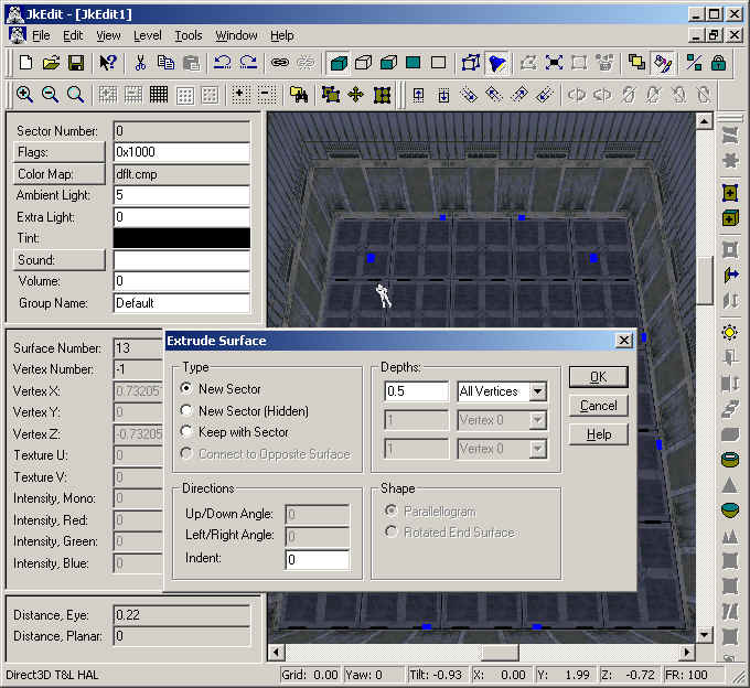
We are now ready to extrude the surface. First we attach the node grid to the surface and select two nodes, button one first. Having done this, we bring up the Extrude Surface dialog. Here we change the Up/Down angle to -15 (negative for down) and the Left/Right angle to 10 (positive for left):
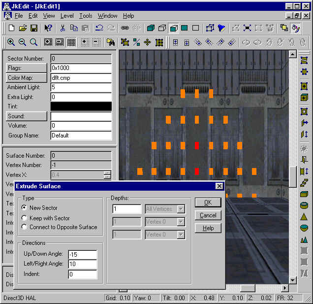
By clicking the OK button we accept the extruding of the surface, and notice that we now have created a nice little cave:
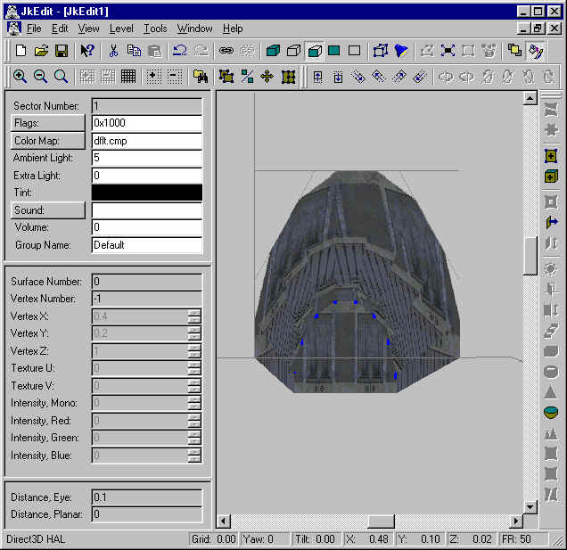
The Split by Polygon command is very useful to create circular, half-circular, or less surfaces, which together with the Extrude command (and two selected node on the node grid) can be used to create all kind of coiled sectors, moving in all kind of directions.
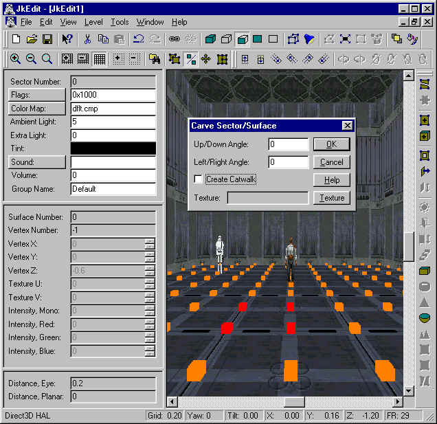
Let us now try to use the Carve function with some angle specifications. First we use the vertical scrollbar to move up towards the ceiling. Here we attach the node grid to the surface and select four nodes in circular order, bottom left first. Having done this, we bring up the Carve Sector/Surface dialog. Here we set the Up/Down Angle to 45 (positive for up) and specify a suitable texture:
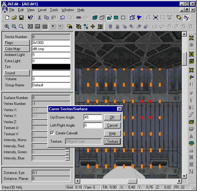
Click OK in the Carve Sector/Surface dialog to create the catwalk. This will cause quite some sector and surface splittings, and we end up with a nice 45 degrees beam to the ceiling:
Now we scroll down a bit and to the left of the cave opening. Attach the node grid to the floor surface and select for nodes in sequential order. Having done this, bring up the Carve Sector/Surface dialog:
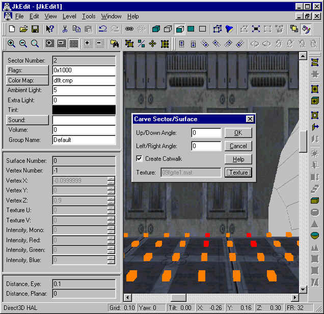
Click OK in the Carve Sector/Surface dialog to create the catwalk. This will cause quite some sector and surface splittings, and we end up with a nice vertical beam to the ceiling:
You have now learned how to use the Carve Sector/Surface tool to make some very nice geometry changes to a sector. By using smart selection of nodes on the node grid, you can control the way a sector is being splitted. Now that you master carving of sectors, you have become a jedi in creating cool levels.
Lesson 14 - Tutorial for Cogs
Cogs are used by the JK or MotS engine for any external action which take place. They tell the program what happens if e.g. Kyle fires his Bryar pistol, how it sounds or how much damage a shot can do. There are other cogs which regulate the AI of the actors and every technical actions like switches, doors or cameras. They seem to be written in C or another similar language and for normal users they are almost impossible to understand. What I try to explain now is the fundamental use of them. After that you can understand what your cog wants to have from you (I hope!), but you won´t be able to write them.
The first cog to start witch is 00_conveyor.cog . I think you know what sectors, surfaces and objects are since you will need that knowledge.
Conveyor looks like that:
# Jedi Knight Cog Script
#
# 00_conveyor.cog
#
# generic conveyor belt script
#
# This script will control 1-8 conveyor belts moving in the same direction
# and with the same velocity. The conveyors run continously.
Now we know what purpose conveyor has and we know what information it needs to work. This cog is used for water falls and moving surfaces in general. The #´s prevent that the cog tries to understand this part, it is only information for us.
symbols
message startup ( not important )
vector vec0 desc=conveyor_direction ( a vector )
float speed=2.0 desc=conveyor_speed ( the surface´s speed )
surface convey0 nolink ( the surface )
surface convey1 nolink
to...
surface convey7 nolink
Everything that comes after that passage is hard too understand and anyhow not important for us. The first two lines tell the engine that the cog starts. Now the interesting part begins: vector vec0 is a sign for us that we have to insert the vector of the surface's movement. A vector with no movement looks like that: (0/0/0). You can see vectors like arrows which point in a certain direction, (0/0/1) is an arrow pointing to the ceiling. If you´d like you water falling down use (0/0/-1) etc. Float speed is (perhaps you guessed it!) the speed of the movement, 2 is just as fast as normal walking. The surface passage tells us that we can move up to 8 surfaces with one single cog. Example for a waterfall: (0/0/-1) 4 45 -1 -1 -1 -1 -1 -1 -1.
Now you know that you can ignore the header (#-passage) and can roughly analyze the structure of cogs. Surface can be replaced by thing (e.g. a console) or sector and so on. In general the name of the cog and the header tell you much about its function. You will see that the normal door-cog can open 4 doors at the same time, you can change the door´s speed and the time it remains open ( sleeptime ). Many things like cameras or lifting shuttles are tricky and therefore you should copy them from original Jk or MotS levels.
Another easy cog is 00_soundtrack.
The essential part:
int starttrack ( the first track to be played, like a cd-player )
int endtrack ( the last track )
int loopto ( the track where the program starts again after reaching endtrack )
Example: 3 5 4
Or 00_slideceiling
float u=10.0
float v=10.0
Every surface which is Sky(Ceiling) in surface flags now moves.
Or 00_elev_switch
surface lower_adjoin0
surface lower_adjoin1
surface lower_adjoin2
surface button
This is a normal cog for an elevator with one call button. If you do not want to use that adjoins, use -1 as their number. Example : -1 -1 -1 14
When looking at that cog you´ll see that there is also the possibility to change the wait time, the elevator´s speed, sleep time and the sound of the button, but as there are already values for that we do not have to insert them.
You see the same procedure with the 00_door cog, which requires the door number and -1 -1 -1.
Summary
1. The title of the cog is a hint of its function
2. Forget the parts which start with a # or "message", but read them
3. Open a Jk or MotS level and try to get a overview about the cog´s function
4. Analyze the structure with the following table:
surface : number of a certain surface, e.g. 12
thing : number of a certain object, e.g. 0
sector : number of a certain sector, e.g. 1
vector : like an arrow e.g. (0/0/1)
float : can be numbers like sleeptime or speed of e.g. a door
flex : similar to float
sound : the sound which is played if you e.g. press a switch
int : I don´t know, in general like float and flex
Kai-Marcus "Bluecher" Peschl (modified by Ole Thomasen)
Lesson 15 - Tutorial for making new Skins
This tutorial will help you changing the skins of already existing 3d objects. Both the skins and the surfaces are mat files which cannot be used by Paintshop Pro or Ms Paint; consequently we need some programs which will decompile them and - before that - extract them from the Jk or MotS resource files. Luckily, JkEdit can do both of these jobs.
Okay, letīs say we want to change the skins of the R5 Droid in MotS:
1.
Start JkEdit and a new MotS level and press insert to open the Templates in Level Dialog; search for R5 and write down his file name as 3do, which is r5.3do. Now select the File Manager and open the MotS resource file ( Jkmres.goo, which you will find in Program Files/LucasArts/MotS/Resource ) and select r5.3do and extract it to a new folder.
2.
Open r5.3do with Wordpad and have a look: you will find there a list of the mats the 3do uses, e.g. its front and back body skins. Write down the mat-file names and open Jkmres with the File Manager in order to extract the mats. Letīs say we want to change the front body skin ( R5BODYFT.MAT ); to do that use the File Manager and find the mat. Now select Save As, having changed the file type to bmp file. This will save the mat file into a converted bmp file.
3.
Start Ms Paint or a similar program, load the bmp file; you should only do modifications to the existing skin, that guarantees that the skin fits. Do NOT change the size of the bmp file.
4.
Rename the bmp-file to e.g. myr5bdft.bmp. JkEdit can compile this file into a mat-file when needed.
5.
Open r5.3do and search for the line with R5BODYFT.MAT and replace it with MYR5BDFT.MAT. Save this file and rename it to myr5.3do.
6.
Now start JkEdit and a new level; open the Template Manager, search r5 and press Add and then Add 3do and select your myr5. Now you have to open Files in Level and add myr5.3do as well as myr5bdft.bmp. When you insert the bmp file, JkEdit automatically converts it to a mat file.
7.
Now you can insert myr5 and test the level.
By the way, when I looked for the wing-skin of the Z-95 Headhunter I found alternative wing-skins which you can use to make that Z-95 a Gold or Blue squadron Headhunter. Nice!
Kai-Marcus "Bluecher" Peschl (modified by Ole Thomasen)
Lesson 16 - Create advanced geometry, III
In this tutorial you will learn how to create advanced geometry in your level using JkEdit.
First we will create a new level, and attach a node grid to the surface in front:
By using the plus and minus button in the toolbar, we make sure the grid spacing is 0.10, which can be seen in the status bar. We select four nodes on the node grid, the bottom left first, and then three more in counter clockwise order:

Now we split the surface by selecting the Split Sector/Surface command, saying yes in the dialog:
We are now ready to extrude the surface. We bring up the Extrude Surface dialog, leaving the default parameters as they are:
By clicking the OK button we accept the extruding of the surface, and notice that we now have created a nice little corridor:
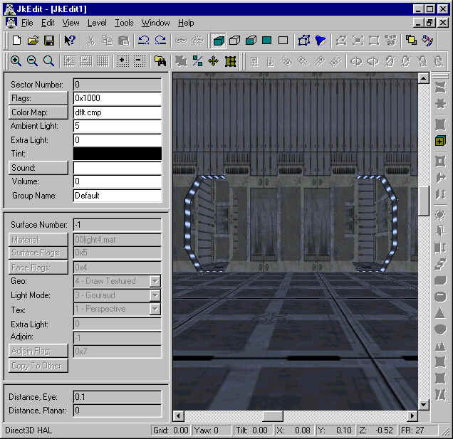
We want to create an invisible opening, i.e. attach a texture to the opening of the corridor such that we can pass through it. In order to do that, we need to alter the adjoined parameters. Select Adjoin Rendering in the toolbar and select the front surface of the opening:
Now change the material, surface flags, face flags, etc to that of a normal surface:
We notice that the surface appears to be that of a normal wall. However, when testing the level in JK or Mots, we notice that we can actually pass through the wall, and from inside the corridor, we can see right through it. If we select the Surface Flag 'Enemy Cannot Walk', guess what will happend.
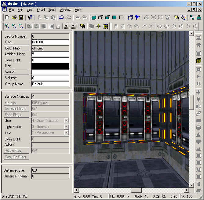
Lesson 17 - Create smooth corners
In this tutorial you will learn how to create smooth corners using JkEdit.
First we will create a new level, move to a corner, and attach the grid node:
We select 4 vertices in clockwise order, starting with the lowest left corner, followed with splitting the surface (s):
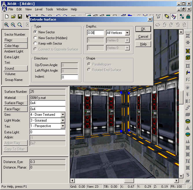
After the splitting, we use the extrude command to create a new sector of depth 0.08. After this we change the textures:
Now we do the same at the left corner surface:
We notice that the corner edge between the two new sector is solid. However, we can easily fix this by extruding one of the corner edges with the same depth of 0.08:
This leave us with a thin surface between the new corner sector and the left corner sector:
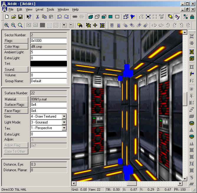
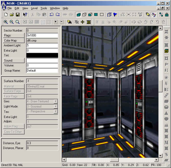
However, we can again easily get rid of this by linking it. After this we just need to copy/paste the texture:
Lesson 18 - Create advanced geometry, IV
In this tutorial you will learn how to create advanced geometry in your level using JkEdit.
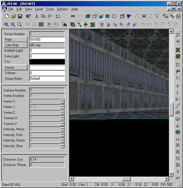
First we will create a new level, and attach a node grid to the surface in front:
We select two nodes on the node grid, the bottom node first, followed with selecting the Extrude dialog:
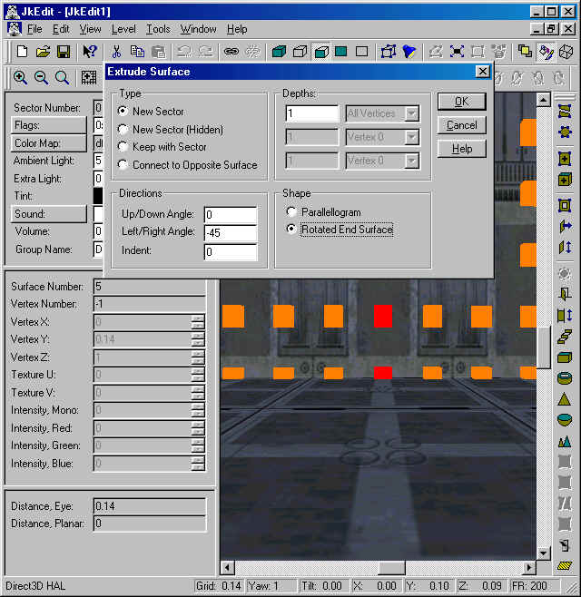
Notice the selecting of a Left/Right angle of -45 degrees. This corresponds to having the new sector rotated 45 degrees to the right. We also specify Rotated End Surface. This corresponds to have the end surface of the new sector rotated as well. We can now proceed with creating the new sector:
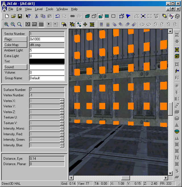
In this new sector the new end surface will have an angle of 90 degrees from the original front surface, since the rightmost side surface is rotated 45 degrees and the new end surface is rotated 45 degrees along the rightmost side surface. We attach a node grid to the new end surface:
Now we repeat the Extrude procedure as mentioned above once. This will result in a half circular set of sectors:
Now we perform a normal Extrude procedure and create an extended sector with the depth of 2, just like the original sector we started in:
If you take a closer look at this new sector's end surface, you will notice that is is exactly aligned with the very first start sectors end surface. In order to make a full circle, we just have to do two more extrudes, specifying a Left/Right angle of -45 degrees, and Rotated End Surface:
The final end surface happens to be exactly back-to-back with the very first sector's end surface. Since we want to connect to that surface in order to have transparent passage, all we need to do is to select the final end surface and then select Link (ctrl L):
This is the easiest way to create a circular set of connected sectors. But what if the final end surface is not exactly back-to-back with the starting end surface? In order to study that situation we just perform two undo operations:
Now we do one more Extrude specifying a Left/Right angle of -40 degrees, and Rotated End Surface:
The idea is to connect the two end surfaces, and in order to do that we will have to connect the individual vertices. We decide to connect the vertices in the final end surface to the vertices of the original end surface. First we select a vertex in the original end surface:
Now we press the key to select the vertex in the final surface:
Having selected the second vertex, we can now adjoin the two vertices. We do this by selecting the Link (Ctrl L) option:
Finally, we continue this procedure for the three remaining vertices:
The only thing we have to do now is to link the two end surfaces:
That's it. We are done.
Lesson 19 - Create circular sectors, I
In this tutorial you will learn how to create circular sectors in your level using JkEdit.
First we will create a new level, and attach a node grid to the floor surface. The first node to be selected is right in the middle of the surface (where the player is), and the second one is just ahead.
We then use the Split by Polygon option:
Notice the selecting of radius of 1. This corresponds to half the width of the original room. Clicking OK in the Split by Polygon dialog, we obtain the following surface:
We now use the Extrude Surface option to create the desired circular sector:
This will create the new circular sector of height 0.5. Note that this new sector is sector 1:
We can now move our player and stormtrooper down to sector 1, followed with deleting the original sector, sector 0:
After some texturing and selecting "Scroll On", "Scroll Off" to realign the camera, we end up with a nice rounded sector:
FAQs
- How do I play Jedi Knight/Mots without the CD-ROM?
You can play Jedi Knight or Mysteries of the Sith without the LEC CD-ROM. In order to do that, you must copy the file "Jk_.cd" in the ...\Resource directory on the Jedi Knight/Mots CD-ROM to your hard-drive in directory ...\Resource of the installation folder of Jedi Knight/Mots. Having done that, you must modify the Registry such that "CD Path" points to the file "Jk_.cd" on your hard-drive.
HKEY_LOCAL_MACHINE\SOFTWARE\LucasArts Entertainment Company\JediKnight\v1.0\CD Path
HKEY_LOCAL_MACHINE\SOFTWARE\LucasArts Entertainment Company LLC\Mysteries of the Sith\v1.0\CD Path
As an example, the CD Path for Mots could be:
"CD Path"="C:\\Program Files\\LucasArts\\MotS\\Resource"
- Cannot Find Jedi Knight resources?
If you see the above message when you start up JkEdit, you need to either insert the original Jedi Knight/Mots CD-ROM in your CD drive, or do a FULL install of Jedi Knight/Mots from the original LucasArts CD-ROM. Another possibility can be that you have started JkEdit after Jedi Knight or Mysteries of the Sith is still running. In this case, close down Jedi Knight or Mysteries of the Sith, and then try to start JkEdit.
- I keep getting the error "D3DIM700.DLL. Why?
If you see a crash when you start up JkEdit, and the crash message says it cannot find "D3DIM700.DLL", this is because you have not installed DirectX 7.0. JkEdit requires DirectX 7.0, which you can download for free from Microsoft's website at Microsoft.com.
- Why do I have a low frame rate?
You might have a slow machine (less than 200 Mhz) or the Horizon and 3DO Distance in the Option dialog has been set to high. These parameters are used for specifying how far away from the camera, surfaces and objects are to be rendered. By lowering the Horizon and 3DO Distance to e.g. 1.0, only a few surfaces close to the camera will be rendered, resulting in a higher frame rate.
Another possibility is that the Stretch Factor in the Option dialog is set to high. Try with 320x240, this will cause JkEdit to use a small internal memory block for 3D rendering, thus giving you a higher frame rate.
Turn off Object Rendering while you are creating your level. If your level contains a lot of 3DO objects, you will see a huge improvement in performance.
Also check to see if you are operating in RGB mode. Try in the Option dialog to change DirectX Device to Direct3D HAL (Hardware Abstraction Layer). If your hardware have sufficient 3D acceleration features, you will now enter Direct3D HAL mode, giving you a much higher frame rate. If not, you should consider to purchase a new video board.
Finally, turn collision detection on, and run the Hidden Sector Removal command with Distance 1 and Level of Detail 5.
- How do I create a new sector?
You make a new sector by extruding an already selected sector. The new sector will have a front and an end surface identical in size to the original selected surface. A set of side surfaces will be created between the front surface and the end surface. These side surfaces will consist of four vertices each. The front surface will be adjoined to the original selected surface.
You can also try to expand a selected surface. This will give you a sector in continuation of your selected surface, and the new sector can be larger in width and height than your original sector.
There are also other methods to create sectors, like Create Door, Create Elevator, Create Cylinder, Create Dome, etc.
- Why do I see HOM effects when I run my level?
Hall Of Mirrors effect are general caused by errors in your level. Typically you have violated the convex constrains required by the Jedi Knight/Mots engine. The convex constrains requires all angles between neighboring surfaces to be less than 180 degrees, and also that surfaces within a sector all have an angle between them less than 180 degrees.
Another option is, that you have made an opening between two adjacent sectors, but have not created any adjoined surfaces between the two sectors.
You could also have cog's specifying wrong surface numbers. This will typically be the case if you have split some surfaces, after creation of your cog's.
Finally, if you have made some cool sectors with strange angular shape, the Jedi Knight/Mots engine cannot cope with the generated collide box. For the sectors in question, just turn off the sector flag "Contains Collide Box".
- Why do my 3DO objects freeze?
Freezing of objects are general caused by errors in your level. Typically you have violated the convex constrains required by the Jedi Knight/Mots engine. The convex constrains requires all angles between neighboring surfaces to be less than 180 degrees, and also that surfaces within a sector all have an angle between them less than 180 degrees.
- What limits does the non-registered version of JkEdit have?
The non-registered version of JkEdit contains the same functionality as the registered version of JkEdit. The only difference is, that the non-registered version contains limits for how many sectors, surfaces, vertices, and objects you can add to your level.
- When I insert cog's, Jedi Knight/Mots crashes, or I see HOM effects. Why?
Take a good look at the cog scripts, they very likely contains some references to materials, sounds, or templates. Your level may not contain those. Check the material dialog, and add the materials if necessary by selecting an existing surface. You can always repair the surface afterwards with its original material. Do the same for the templates. And for the sounds, just add the missing sound to a sector, one by one, you can always remove the sound from the sector again.
Another possibility is, that you have not specified the correct parameters to your cog. Make sure that surface numbers and object (things) numbers are correct.
- How do I make a multiplayer level?
In order to make a multiplayer level, you must modify the Episode Editor. Change the Type parameter to "Multi Player". The maximum number of players allowed to join the game is defined by the number of "walkplayer" in your level. If you want e.g. max 4 players, you must insert 3 more "walkplayer" in your level. Just click on the current one and press the Ins key. This will insert another player.
- When I approach a 3DO object it disappears. Why?
Make sure the Sector parameter of the 3DO object corresponds to the sector around it.
- How do I make multiple levels in JkEdit?
JkEdit has a great tool for that. With no level files open, select the Tools menu, and select the Multiple Level Editor. You will have to study the help system for this dialog carefully.
- Why are some textures, doors, or elevators pink?
All textures in Jedi Knight/Mots requires a certain palette in order for the colors to show up right. There are several palettes available, and if you see a pink texture, door, elevator, etc, it simply means that the current palette won't work with that texture. Change to another palette (for the sector). Also keep in mind, that the original LEC levels uses different palette per level.
- How do I make Lightning effects?
There is basically two kind of lightning effects. If you assign Ambient Light or Extra Light to a sector, this affects how 3DO within that sector are lit. If you want to alter lightning for the sector itself, i.e. its surfaces, you will have to assign intensity values to the vertices within the sector. Select the Light Mode option (toolbar button). Now select a vertex and select the Create Light option (toolbar button). This will do it. If no vertex is selected, the Create Light option will distribute the intensity value to ALL vertices within the sector.
- How do I change to HAL mode?
JkEdit can operate in two modes, HAL and RGB, the latter meaning that 3D rendering is done in software. If you change to HAL mode, JkEdit will use 3D acceleration (Hardware Abstraction Layer), which will give you much higher performance. You change from RGB mode to HAL mode by changing DirectX Device in the Options dialog. In order to change to HAL mode, your screen settings MUST be High Color (16 bits) (and NOT 256 colors). Having set your screen settings to High Color (16 bits), you still may see an error message saying your video board don't have enough video memory. In this case you can either reduce your screen resolution or buy a new video board.
- Why can't I get the Grid to show up?
If you cannot get the grid to show up on a surface, perhaps you should check your Grid Distance in the Option dialog. If your camera position is further away from the surface in question than the Grid Distance, then the grid nodes will not be rendered. Simply set the Grid Distance to a higher value.
- How do I create a customized door or elevator?
The Create Door and the Create Elevator command can be customized to contain further selections. In order to do this, you must add a proper template to your level by using the Template Manager. Select an existing template like e.g. 2x3door or 3x3elev and click on the Add button to create a new template entry. Make sure the name for the new template contains the letters "door" or "elev".
If you want your own 3DO to be the actual door or elevator, then you must modify the parameters accordingly. In this case you must also remember to add your 3DO to your level using the Files In Level command.
Having done this, your customized door or elevator will now show up in the Create Door or Create Elevator dialog.


well done in helping preserve history and keeping Dark Forces II alive
I was particularly inspired to post this since there are no other tutorials for this program. Outside of the help file that just lists what all of the various buttons on the UI do.
great job uploading this again. I tried using this software on windows 10 and the app crashes after selecting the JKMRES.goo file from the resource. How do i resolve this?
I'm not sure as it runs just fine on my machine on Windows 10. I released a tutorial today on how to run it via the GOG/Steam port.
Moddb.com
Love to see this game still active.
Great and contemporary stuff going on at JKHub.net
check it out!!!
There's an engine recreation being produced called Smith