This is an official tutorial on how to create outdoor levels for Motocross Madness 1. Created by Rainbow Studios. You can find the official tools here. Note not all the images were archived but much of the information here has now been preserved.
Overview - Creating Motocross Madness Outdoor Tracks
The purpose of this document is to define how to create outdoor style tracks for Motocross Madness. Out of the box, MCM supports the creation of indoor Supercross tracks. The Supercross track editor is very easy to use so it's use is not covered here. The SX editor also supports the creation of additional plug-ins called contruction sets. Creating those construction sets is also NOT covered in this document. That information will be published at a later date (when Robb gets around to it).
Motocross Madness 1.0 supports two styles of outdoor terrains: Nationals, and Stunt Quarries. The Nationals terrain are used for racing Nationals style races. The Quarry style terrain are used for Stunt Quarries, Baja races, and Tag.
In order to create the content that goes into building an outdoor track, you will need several third party applications such as a paint program, and a 3D modelling program. The programs you select for various tasks is not important, as long as they support the correct file formats used by our build tools.
Here are the tools that we use at Rainbow Studios:
2D Paint: Adobe Photoshop, Picture Publisher, Paint Shop Pro
3D modelling: Studio Max, Lightwave
Text Editing: Notepad, Wordpad
Here are the file formats used to create tracks:
Image Formats: 24-bit Targa (.tga)
Geometry Formats: ASCII (.asc)
Text Files Formats: Text (.ter,.scn, .txt)
Utilities needed to perform various steps:
Tergen.exe - Utility used to create a skeleton terrain definition file (.ter) without having to do a lot of typing.
Tga2Asc.exe - Targa file to ascii file conversion utility. This program takes displacement maps in .tga form and converts them into the .asc file format used by the terrain compiler.
MakeTerr.exe - Terrain compiler. This file ships with Motocross Madness. It's located in the ...\trakedit directory. It's actually used to compile Supercross tracks as well as outdoor Nationals and Stunt Quarries.
TrackConvert.exe - Converts text files containing track path data into .dat files used in the game.
Grid plug-in for Studio Max - Charityware grid plug-in used in 3D Studio Max to create a grid of polygons.
TrackBastard plug-in for Studio Max - Rainbow's Max plug-in for creating the track's spline path.
MakeCub.exe - Utility used to create sky cube files (.cub)
File and Directory Structures
The default installation path for Motocross Madness is C:\Program Files\Microsoft Games\Motocross Madness. You could have installed the game to any location. For example, I've installed the game to D:\MotocrossMadness on my machine. All of the directory information presented here is relative to the base directory you chose during the game's installation.
All the tracks are located under the ...\teraform directory in different directories by track type:
...\teraform\national - contains nationals tracks
...\teraform\quarries - contains stunt quarries
Each new track you create requires 4 new files. These 4 files all have the same base filename and four unique file extensions.
Outdoor tracks require 5 files to function within the game:
1) .TRN - This file contains the compiled geometry and texture data. Most .trn files are around 5-6 mb. These files are created by the MCM terrain compiler called MakeTerr.exe.
2) .SCN - This is a text file that contains environmental information about the track such as the sun position and color. You create this file using a text editor.
3) .TGA - This image is used in the game's user interface to visually select the track. You create this image by performing a screen grab in the game, then cropping and scaling the image to the correct size in a paint program.
4) .DAT - This file contains the spline path and track width information for the track. This file is created using the MCM Track Converter utility called: TrackConvert.exe.
5) .CUB - This file contains the image data for the sky. You don't have to create this file. Your .scn file just has to reference an existing sky cube file. You can create your own sky cube files, but then you HAVE to distribute 5 files instead of 4.
After racing on a track you will also notice that a few more files of the same name have shown up:
1) .AID - This file contains information that AI riders learned about the track as they turned laps. Each time they ride on a given track, they gain more experience and expertise on that track. Their knowledge is stored in the .aid file.
2) .HIS - This file contains high score information.
Here is an example of a the files used to run a Nationals track:
FLUBBER.TRN (the track itself)
FLUBBER.DAT (track path info)
FLUBBER.SCN (scene layout data)
FLUBBER.TGA (image used in user interface)
If you made your own custom sky cube to go with you FLUBBER track, you would need to distribute it too:
FLUBBER.CUB
Basic Steps to creating outdoor tracks
This section will present the basic steps involved in building a track, along with some explanation of the content you have to create. The way the tools are designed, there are actually several ways you can create the data for your track. The simplest way involves only using 2D paint programs. But unless you are a superb artist, its fairly challenging to get good results. The slightly more complicated method involves the use a 3D modelling program like 3D Studio Max.
Don't worry about the particulars of these files, we'll get to the details in following topics.
To build your own track, you need to create the following content:
- A height field map in one of two forms: either a displacement map (.tga) or a 3D model (.asc). If you choose the displacement map technique, you have to paint the map by hand using a 2D paint program like Photoshop. If you choose to make an .ASC file, this is done in a 3D modelling program like 3D Studio Max.
- A single high resolution texture map that is draped over the terrain. This .tga file can be hand painted in a 2D paint program, or rendered in a 3D application. Using a 3D program will allow you to create accurately raytraced shadows that will match the riders real-time shadow that is cast during game play
- A terrain definition file (.ter). This is a text file that is structured in the popular Windows' .ini format. The .ter file defines all source files that the terrain compiler (MakeTerr) will use in the construction of a compiled track (.trn).
- A small tillable texture map (.tga) that surrounds the perimeter of nationals tracks. This additional texture map is NOT used in the creation of stunt quarries, just nationals.
- Once you have created these files, use the MakeTerr utility to compile the track (.trn). MakeTerr uses the .ter file you created to compile your source material into a playable .trn file.
- The last step before you can test out your new track is to create a scene file (.scn). The scene file is a text file that informs the game about various things relating the environment including: the name of the .trn file, sky.cub file, sun x-y-z location, sun color, fog color, and lots of other parameters.
- At this point you can test out your new track, even though you haven't created some important items like the the track's spline path. This is the perfect time to try out a few laps, and see where the track might need some work. Learning to space out the jumps and control the angles of the jumps takes some practice, so you'll probably make lots of iterations on your track before it's really ready to race.
- Once you're happy with basic structure of your new track, you can finish the track by creating the spline path file (.dat) using Rainbow's TrackBastard plug-in for 3D Studio Max.
- The very last step is to do a screen grab from within the game to get a nice image of the track to use in the game's user interface track selection screen.
The next few topics will go into the details of each the steps outlined above.
Technical Overview
This document will introduce the technical details behind Motocross Madness outdoor terrain files.
To simplify the amount of typing and reading here:
Microsoft's Direct 3D is referred to as "D3D"
3D Studio Max is referred to as "Max".
3D Coordinate Systems - Can Anyone Ever Agree?
It seems every 3D program you use these days uses a different 3D coordinate system to display 3D objects. In the case of Motocross Madness, we require the use of two programs with varying coordinates systems (illustrations are seen from "Front" viewport, not the "Top"):
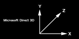
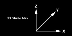
It's confusing, so be careful when collecting data from 3D Studio to use in your scene files. A good method is to write everything down on paper using Studio Max coordinate system, then type the data into your scene files in D3D format. The simple version of the differences between the two is that Y and Z are swapped. A coordinate of 10,20,50 in Max becomes 10,50,20 in D3D's coordinate system.
The scale system used is 1.0 units = 1.0 feet. So 20.5 Max units is the same as 20.5 D3D units, which is 20.5 feet. This part can be kind of confusing too because we model things in Max smaller than they become in the game. The good news is the that scale units are the same.
MCM's 3D World - Welcome to the Center of the Known Universe
At the center both Nationals and Quarry type terrain is a giant chunk of terrain called a 1x1 (pronounced one-by-one). This chunk of terrain has the following characteristics:
- 256 x 256 x 2 faces or 131,072 faces
- 257 x 257 points or vertexes across
- when viewed from the top viewport looks like a perfectly uniform grid
- in Max it is 256 x 256 units (feet) across
- in Max it is centered at 0,0 so it spans from -128 to +128
- no part of the track can dip below an altitude of 0.0 ( all Max Z points must be >= 0)
- in the game each 1x1 is scaled up 768x768 feet square by the MakeTerr terrain compiler
3D World Layout - Nationals Tracks
A Nationals track is commonly known, in Rainbow techno speak, as a 5x5 (pronounced five-by-five). This is because of the way the data is laid out in our world. At the center of this giant 5x5 collection of terrain chunks is the original 1x1 track, as in the above example, Pitfall.
Surrounding the center 1x1 are 8 identical copies of the center terrain. These 8 surrounding copies of the track are displaced at a significantly lower elevation strength, so they appear like flattened out versions of the track in the middle. You've probably noticed this if you've explored off the main track after a race.
Here is sample image to illustrate the 5x5 Nationals layout:
By studying the sample layout below, you can see that the Pitfall track is directly in the center a the 5x5 collection of terrain chunks. It it surrounded by 8 copies of itself. Around those 8 copies are the edge of the world geometry. We call Nationals tracks 5x5's because the entire world is composed of 25 giant chunks of terrain arranged in a 5 by 5 grid.
3D World Layout - Stunt Quarries
A Stunt Quarry is almost identical to a Nationals track with the exception that there is another row of terrain chunks surrounding the 8 that already surround the center piece. All together there are 49 giant terrain chunks that make up a Stunt Quarry, hence in Rainbow speak, 7x7's (pronounced 7-by-7's).
The 24 terrain chunks that surround the center 1x1 of terrain, are not all flattened out like in the case of the Nationals. These 24 terrain pieces are elevated at varying heights (including negatively displaced which turns them inside out) to create the illusion of a large land area.
Surrounding these 24 chunks of terrain are the edge of the world geometry, just like the Nationals tracks.
Interesting Side Bar: So if each 1x1 terrain chunk is 131,072 faces and there are 49 chunks of 1x1 terrain in a Stunt Quarry, then there a total of 6,422,528 polygons total in a single Stunt Quarry. Its fairly amazing that the game can maintain rendering 30-60 frames per second on a fast Pentium II machine. Obviously, the game doesn't render all 6 million polys on every frame, but the code does have to manage that many polygons in just a few milliseconds. And that my friends, is why lead programmer, math genius, and Rainbow Studios' technology leader Mark De Simone is known simply as, "The Man"! Great job Mark!
3D World Layout - The Infamous Edge of the World
Before reading this section, its important to know that making your own custom edge of the world geometry is COMPLETELY OPTIONAL. If you don't want to learn about this you don't have to. We suggest you choose to use the edge of the world geometry provided in the sample tracks. That way your custom tracks will match the exact style of the edge of the world geometry found in the game.
Making good edge of world geomtry that works well within the game, and actually compiles correctly is pretty tricky. In case you are wondering why we went to all this trouble, its a memory limitation. We had to keep the game running in 16mb of memory, and we didn't want a cheesy fence stopping you at the edge of the world.
In the context of a Nationals track. As long as you stay on the track, the game provides excellent visibility into the distance without any apparent limitations. If you do decide to venture off the track, you have to go quite a ways before reaching a barrier of some sort. Originally, the giant cliffs at the edge of the world were meant to be unclimbable, but that didn't last long. With a little practice you can quite easily make it up the cliffs. Almost everyone who plays the game has experienced what happens if you manage to climb the cliffs and keep on going. KA-BOOM! What we ended up shipping was a really fun way of dealing with the problem of keeping the rider within the boundaries of our 3D world.
The sample image here shows how the edge of the world geometry is broken up:
Each edge of the world chunk of terrain has the following characteristics:
- 128 x 128 x 2 faces or 32,768 faces
- 129 x 129 points or vertexs across
- when viewed from the top viewport looks like a perfectly uniform grid
- in Max it is 128 x 128 units (feet) across
- in Max it is centered at 0,0 so it spans from -64 to +64
- no part of the edge of world geometry can go below an altitude of 0.0
The edge of the world geometry requires 9 separate pieces of geometry to make it work:
1) the outside edge. In the game this is the flat part up high once you've climbed the cliffs. You can drive about half way across the outside edge before the cannon launches you toward the center of the world. This piece is tiled all around the outside edge of the world.
2) Northwest corner piece. This piece must connect seamlessly with the North, West and outside edge pieces
3) North side piece. This piece tiles along the north side of the world and must connect seamlessly with the Northwest, Northeast and outside edge pieces.
4) Northeast corner piece. This piece must connect seamlessly with the North, East and outside edge pieces
5) West side piece. This piece tiles along the west side of the world and must connect seamlessly with the Northwest, Southwest and outside edge pieces.
6) East side piece. This piece tiles along the east side of the world and must connect seamlessly with the Northeast, Southeast and outside edge pieces.
7) Southwest corner piece. This piece must connect seamlessly with the West, South and outside edge pieces
8) South side piece. This piece tiles along the south side of the world and must connect seamlessly with the Southwest, Southeast and outside edge pieces.
9) Southeast corner piece. This piece must connect seamlessly with the East, South and outside edge pieces
Displacement Map Basics
The foundation of each track you make is a displacement map.
Question #1: What is a displacement map?
Answer: It's a greyscale image that you create by painting in a paint program like Photoshop. A greyscale image contains pixels that range from white to black with all shades of grey in between. The shades of grey in the image relate to the height of points on the terrain. The dark values are low points in the terrain and the bright values are the high points in the terrain.
A short discussion about color space might be in order. The most popular color space used in paint programs today is the R-G-B color space model. In this model each primary color value (red, green and blue) is represented by a numeric value ranging from 0 - 255, where 0 is completely dark and 255 is completely bright. Some examples are: 255,0,0 = bright red, 0,255,0 = bright green, 0,0,127 = blue at 50% brightness, 255,255,0 = yellow (by combining red and green).
Whenever the RGB values are all the same (such as 64,64,64 or 157,157,157) what you get is a grey pixel. So in a greyscale displacement map, all the color values have equal red, green and blue values.
Important: In Photoshop, your image needs to be "mode type" RGB, not greyscale. Even though the image you are painting is grey scale, make the image mode type RGB and save it as a 24-bit image.
![]()
Interesting Side bar: Traditional artists that paint on canvas are probably freaking out right about now because everything I've just explained goes against the way you mix paint to create colors. The difference between our analog world, and the digital computer is this: In the real world, we see subtractively where everything looks white until the surface properties of objects absorb certain spectrums of light. Everything an object doesn't absorb bounces back to our eye and we see as color. In the computer, everything works additively where you start with RGB 0,0,0 (black) and begin adding hues and luminance to create color. If our computer monitors were pure white when we turned them off, then the computer would function pretty much like real life. So the simple version is: real life subtracts color from pure white to create color, whereas the computer adds light to black to create color. Kinda cool huh?
Displacement Map Details
- The color depth, resolution and image format you paint the displacement map in is not particularly important. Most of the maps created at Rainbow were painted in Photoshop as a multi-layer Photoshop document, or .PSD file.
- The aspect of the source image should be square.
- We recommend painting your image at a resolution of about 512x512 or 1024x1024, but this is for your visual convenience only.
- After saving your source displacement map, you should resize the image down to EXACTLY 257x257 pixels and then "Save a copy...." as a 24-bit targa file. It's critically important that your image be precisely 257x257 pixels and that is a 24-bit targa file, not 16-bit and not 32-bit with alpha channel
- Painting the displacement map at higher resolution is easier to see on the monitor as you paint, resampling the image down to 257x257 helps smooth the surface of the map. Bumpy terrain is not at all fun to ride on in the game.
- The edges of the displacement map MUST all be exactly the same color. This creates a flat edge all the way around the perimeter of the track and facilitates each section of terrain connecting seamless with it's neighbor.
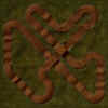
Here is a sample displacement map from Motocross Madness. This image is the displacement map that became the Nationals track known as "Custer's Last Stand". Note: the sample images on these pages are compressed .jpg files, so things like all the edge pixels being the same value (as outlined above) might not be true due to the fact that JPG is a lossy compression. You shouldn't use these actual images to do any production work with. Use the images in the provided sample tracks downloads.
Question #2: How do I know how the greyscale values in my displacement map translate into height values in 3D world space?
Answer: The black values in your displacement map equate to 0.0 feet high in 3-space, and pure white values (RGB 255,255,255) equate to a height value you specify. The way you specify the scale differs depending on the method you use to convert your .tga file to an .asc file. The following section answers this question in greater detail for each method.
Question #3: How much actual land area will this displacement cover in 3D world space?
Answer: In the game, a 1x1 chunk of terrain covers 768 by 768 feet. An entire 7x7 stunt quarry is then 5376 x 5376 feet across.
Making ASC Files From Your Displacement Map
Once you have finished painting your displacement map at high resolution and saved a scaled copy of the image as a 257x257 24-bit targa file, there are two ways you create your .asc file.
Method 1 - Using the Tga2Asc.exe command line utility
The purpose of the Tga2Asc utility is to convert a 2D image such as your 257x257 targa file into a 3D terrain model in the popular .asc file format.
To use this utility, you need to open an MS-DOS command prompt session. You can do this by clicking on the "Start" menu on your task bar, choosing "Run..." and then typing "command" and pressing enter. This will open what is commonly known as a DOS box, or command prompt.
If you place the tga2asc.exe in your "path" you will be able to access it from any directory by simply typing the name of the program (tga2asc), otherwise you will have to have a copy of the utility in the same directory as the targa file you want to convert.
You can see all the command line arguments available simply by running Tga2Asc.exe with no command line parameters.
The command line parameters for Tga2Asc.exe are:
Tga2Asc InputTarga.tga HorzGridSpacing MaxHeight > YourNew.asc
For example: Lets say you have a 257x257 targa file named SILLY.TGA and you want to convert it to an .asc file named MYNEW.ASC where the brightest values in SILLY.TGA will become 15 feet tall peaks in the .asc file. You would use the following command line:
TGA2ASC SILLY.TGA 1 15 >MYNEW.ASC
In the above command line:
TGA2ASC is the name of the utility
- SILLY.TGA is your source 257x257 24-bit targa file displacement map
- 1 is the horizontal spacing between the points of your grid. (This should always be 1)
- 15 is the height that you want brightest (RGB 255,255,255) values in the .tga to translate into feet in the .asc file so an RGB of 127,127,127 would yield a height value of 7.5 feet.
- >MYNEW.ASC will send the output of Tga2Asc to a new .asc file named MYNEW.ASC
Note: The ">" character that precedes the MYNEW.ASC is an old MS-Dos symbol called re-direction. By default, Tga2Asc will just dump its output to the screen, which isn't must good. Using the re-direction symbol ">" followed by a valid filename will cause MS-DOS to re-direct a programs output to a file. So you always have to put the ">" right before the name of the output .asc file to get it to work correctly. The ">" is NOT part of the filename!
Method 2 - Using 3D Studio Max
Using 3D Studio Max is slightly more difficult then using Tga2Asc, but has a number of advantages. The most significant advantage is that once you've setup the grid and applied the displacement map to your grid object, you can then use this geometry to light and texture your track. This then allows you to easily create the high resolution texture map that drapes over the terrain in the game, complete with ray traced shadows.
Note: In order to complete these instructions, you must already have the Charityware Grid Plug-in installed in your copy of Max.
- Make sure your scale units is set to 1.0 units = 1.0 feet
- Launch Max and start with a new project
- Create a new Charityware Grid object
- Adjust the grid object so it is 256 length segments by 256 width segments
- Adjust the length and width parameters to 256 by 256 as well
- Center the grid object at 0,0,0 so it spans from -128 to +128
- Add a Displace modifier to the grid object
- Set the Strength to 15.0
- Assign your 257x257 version of your displacement .tga to the bitmap
- Set the blur strength to between 0.2 and 0.3
You should see the Grid object take the shape of your track. From the top view, it should still appear as a perfectly uniform grid. But from the perspective view you can see the shape of the peaks and valleys.
The last step is to output the object as an .asc file.
- Activate the Toolbar panel and choose ".ASC Output" utility.
- Click the "Pick Object" button and then click on the grid object.
Relevant Additional Knowledge About Displacements
Question: Why do I make grid that is 256x256 feet in my 3D program, when the same terrain covers 768 x768 in the actual game.
Answer: The reason is due to the fact that as we were coding the game, we didn't know for sure exactly how big we wanted a track to be. A lot depended on the outcome of the physics model which was concurrently under development. But we had to start modelling track before the physics model was final. We decided early on to model everything at 256 feet square, then scale everything up by an adjustable amount until the size of the terrain worked will with performance of the physics model. As it turned out, a scale of 3.0 works really well. This means that everything you model in Studio Max gets scaled by a factor of 3 by when you run the terrain builder.
This is important: Not only does the land area get scaled up from 256 ft. sq. to 768 ft. sq., but your hills that were up to 15 feet tall in 3D Studio, will be up to 45 feet tall in the game.
Of all the parameters that we've been carving in your brain as "in stone", using a strength of 15 in your displacement is not one of them. All of the more planar, or flat, tracks we made used the standard "maximum height" value of 15. Bela's Bluegrass was the last track we made, and the first track to be based on the concept of a track being built on a hilly piece of terrain. Brian used a displacement strength of 30 in 3D Studio, so the hills in Bela's Bluegrass are as much as 90 feet tall. Now that you know this, * PLEASE * don't get carried away with making the world's tallest track. Remember, the steeper the terrain, the less the engine can optimize polygons to keep the frame frame high. Bela's Bluegrass is really pushing it as is!
Question: How well does the terrain engine handle extremely jagged surfaces?
Answer: The engine can handle rendering jagged terrain fine, but it will drive the polygon count through the roof and your frame rate will go in the toilet. This is bad. Don't make jagged terrain! The general flow of your terrain should be smooth and flowing. Abrupt changes in the terrain reduce the terrain engine's effectiveness at managing polygons and will drive the polygon count up by the thousands.
Question: I want to have perfectly vertical cliff walls in my terrain. How do I do that?
Answer: You can't. Our terrain engine does not handle angles greater than 89.9999999 degrees steep. That means no perfectly vertical cliff walls and no cave-like structures. Another good reason why NOT to have extremely steep surfaces is due to the way the ground texture image is mapped onto the terrain. The terrain texture is planar mapped directly from the top, surfaces that are too steep will tend to have only one or two pixels representing them in the texture map and will therefore stretch real bad across those steep faces and generally look unacceptable.
Question: What is "overdraw" and why do I care about lots of deep canyons?
Answer: Overdraw is an issue that can also kill the frame rate of a 3D game. In order to construct a complete picture on the screen, the 3D card in your computer may have to render each individual pixel on the screen more than once. For example, lets say you have a simple image where the camera is looking at the terrain in the foreground and there is a single bike and rider sitting there in clear view. The 3d card has no idea what actually covers up what in the 3d scene on each frame as it renders images. There's this thing called that Z-buffer that automatically manages how objects get laid on top of one another in a 3D scene. So the terrain engine renders the terrain, and on this frame the terrain happens to fill the entire screen. But then it has to render the bike and rider on top of the already rendered terrain. So the 3d card is now rendering over top of pixels it already rendered once for this image. Everywhere the 3D card is rendering pixels two or more times is called "Overdraw".
In the above example, the amount of overdraw introduced by a single bike and rider sitting on top of the terrain is completely trivial. They may occupy about 5% of the total pixels on the screen. A little bit of overdraw is always a factor in real-time 3d rendering.
Overdraw becomes a serious performance issue when you start making terrain filled with lots of canyons. An excellent example of some tracks with bad overdraw issues are Airborne Delivery and Dirt Devil. Both of these tracks have canyon after canyon within them with very high walls. Anytime the you are near the edge of the track, looking out across the rest of the track, all the canyon walls facing the camera, all the way to the edge of the track in the distance are getting rendered on top of one another. If there are 5 deep canyons across the track, you might be experiencing up to a 5.0 times overdraw factor. That means the 3d card has to render the entire screen 5 times to get one complete image on the screen. You can imagine what that does to the performance of the game.
Question: Do I really have to make all the edges of my displacement map the same color all the way around?
Answer: Absolutely! In order to take a 1x1 chunk of terrain and make it connect with additional copies of itself that are displaced at lower elevations, the edges must be flat. Sorry, but that's the way its designed.
For those of you who have the screwed up track named "Augusta's Evile Twin", the reason the terrain is screwed up around the edges is because the edges of the displacement don't match up. That also makes the podium appear underground...not to cool.
Note: The Evil Twin itself is really cool. The effect was achieved by simply adding a Wave Noise modifier to the original grid in Max. It twisted the whole terrain in a totally cool way, making the track a really fun challenge to ride. You could fix the edges by writing a max script to look edges of the terrain and force them all the the same elevation, then feather this adjustment in a few points from the edge to smooth out the correction.
Making Texture Maps
The surface of your terrain is covered with an image known as a texture map. This image contains all the details that visibly define the surface of the track.
Texture Map Details
- The application you use to create the texture map is not important.
- A Nationals track requires 4 separate images
- A Stunt Quarry requires on 2 images
- All images must be a 24-bit targa files
- All images must be seamless tillable
The 4 images you need to create for a Nationals track are as follows:
1) The primary 1x1 terrain texture at an exact resolution of 1016 x 1016
2) A scaled copy of the primary texture at a resolution of 504 x 504. This image must be the same filename as image 1, with an "A" appended to the end of the filename. For example, if image 1 is named "MyTexture.tga", image 2 should be named "MyTextureA.tga".
3) A small tiled image that is used around the perimeter of the track. The resolution of this image should be 62x62
4) A scaled copy of the small tiled image at a resolution of 30 x 30. This image must be the same filename as image 3, with an "A" appended to the end of the filename. For example, if image 1 is named "PerimeterTexture.tga", image 4 should be named "PerimeterTextureA.tga".
Here is a sample set of images for you to study. These images are the four textures that compose the Nationals track "Augusta Park". Keep in mind that these images are JPGs, so they've been compressed quite a bit.

![]()
Just in case you're wondering...yes, images 1 & 2 are the same image, only image 2 is scaled to from 1016x1016 down to 504x504. And yes, images 3 & 4 are the same image, only image 4 is scaled down from 62x62 to 30x30.
Important: If you are making a Stunt Quarry you DO NOT have to create images 3 & 4, only image 1 & 2.
The reason why you have to pre-create duplicate images at different resolutions has to do with the way 3D hardware bi-linear filters images at run-time. When you have an image that is tillable, and you scale that image down, all the edge pixels need to be sampled against pixels at the opposite edge of the image in order to keep the image tillable after scaling. 3D hardware does not take this into account as it scales images during real-time rendering. By preparing the highest and second highest resolutions ahead of time, our processing tools (MakeTerr) can work around this hardware limitation and keep your images from having seems show up in the game.
Rendering Ray-traced Shadows in 3D Studio Max
If you choose to paint your texture map by hand, you will not be able to make the shadows in the game match up properly with the bike and rider shadow. It is not a 100% requirement that you take the time to do this, but we prefer that you do. A lot of development time and effort went into making the game support real-time raycast shadows that match the shadows within the environment perfectly. So we'd really appreciate it if you would respect that and take the time to set up the shadows in your terrain precisely.
If you created your displacement map in 3D Studio, then your ready to map your terrain, set up the lighting, and render out a nice high resolution texture map.
Once you've got your terrain mapped and your happy with basic look of it, you'll want to set up the lighting in Max in preparation to render the shadows that will match up with the in-game shadows. There a several limitations as to where you place the light in Max that relate to how well the shadow of the bike and rider will function in the game.
- The type of light you should use in Max is called a "Target Spot Light". Do not use a parallel light.
- I suggest that you render your texture out in Max at about 2000x2000. This way you can go into Photoshop and do additional painting cleanup, like making it tillable, prior to scaling it down to 1016x1016.
- A nice effect you can add in Photoshop to give the look of the terrain more natural variety is to add a new layer in the image, then use the Photoshop "Clouds" filter to create a random clouds images. The composite the clouds image over top of your rendered image using one of the various compositing methods, like Lighten or Darken at about 15-25% opacity. This will add a lot of variety to the way the texture appears in the game.
The simplest way to set up your lighting in Max is to choose from one of the preset light locations provided below:
Important: Don't forget that the x-y-z coordinates represented below have the Y and Z axis swapped between Max and D3D.

For those of you who care to explore setting up your own custom lighting for Nationals tracks, here is the formula you need to convert your Max light position in the correct coordinates for use in the game:
D3D_X = ( MAX_X * 3.0) + 1920
D3D_Y = (MAX_Z * 3.0)
D3D_Z = (MAX_Y * 3.0) + 1920
Use one of the following presets for Quarry style tracks (7x7's)

For those of you who care to explore setting up your own custom lighting for Stunt Quarries, here is the formula you need to convert your Max light position in the correct coordinates for use in the game:
D3D_X = ( MAX_X * 3.0) + 2688
D3D_Y = (MAX_Z * 3.0)
D3D_Z = (MAX_Y * 3.0) + 2688
If you decide to set up your own lighting:
- Keep your light at a distance of about 1000 - 1500 feet from the terrain in Max. This will translate into about 3000 - 4500 feet from the terrain the game.
- Keep the light at a very high angle in the sky. Lighting near sunrise or sunset, where the sun is very low in the sky will NOT work well in the game.
- The one track in the game where the sun appears to be very low on the horizon, Paradise Lost, is an illusion. The visible sun in the sky is very low on the horizon, the 3D position of the sun that is used to calculate the shadows is actually very high in the sky. If you eye ball the shadow of the rider in Paradise Lost, you will notice that the sun you can see in the sky could not possibly cast the shadow of the rider, unless light can bend!
- If you place your light to close to the terrain, the amount of parallax will cause the shadows in the game to only be accurate near the center of the terrain.
- If you place the light too far away, the low spatial resolution of the texture map that we render the bike and rider shadow into during the game will become too low resolution and the rider's shadow will become quite blocky and not look acceptable.
Creating .TER Files
A .TER file is a text based file that contains all the information that the terrain compiler (MakeTerr) requires to assemble a ready to run .TRN file.
Although you can make your own .ter files from scratch, I don't recommend that you do that. The simplest way to prepare to build a track of your own creation is to take an existing .ter file and change just a few lines in the file to make it work for your needs. Make sure that the .ter file you start with matches the type of terrain you are building. In other words, don't use a .ter file that was set up to build a Stunt Quarry and try to build a Nationals track, or vise-versa.
Here is a portion of a .ter file. The sections highlighted in green are the only parts you need to modify to use the file yourself.
[ElevationData]
GridResolutionInFeet=3.0
TerrainType=NATIONAL
TotalElevationFiles=73
TotalTextureMapFiles=2
TotalTexturePlacements=1
TotalTargetWidth=1280
TotalTargetBreadth=1280
ElevationFormat=ASC
ElevationDefault=0
ElevationAtEdge=15.0
TextureFormat=8
ShareTextures=1
ShareGeometries=1
UpPropagateTextures=1
ElevationPath=v:\motox\brian\quarries\quarry18\
TextureMapPath=v:\motox\brian\quarries\quarry18\

[TerrainPalette]
TotalFileSets=2
NumberOfColors=236
FileSet_1=v:\motox\brian\quarries\quarry18\quarry18.tga
FileSet_2=v:\motox\brian\quarries\quarry18\quarry18a.tga

[TextureMapFile_1]
Name=quarry18.tga
CoverageInGrids=256
PixelsPerGrid=4
[TextureMapFile_2]
Name=quarry18tile.tga
CoverageInGrids=16
PixelsPerGrid=4

... [hundreds of lines deleted here to save space on this web page] ...

[ElevationFile_73]
Width=256
Breadth=256
BaseX=768
BaseY=768
Name=quarry18.asc
IMPORTANT: The above quarry18.asc file would be found 9 times in a complete Nationals .ter file. In a Stunt Quarry .ter file it is found 25 times. You should perform a Search Replace operation in your text editor to substitute "quarry18.asc" with "YourNew.asc" file name!!!

Base=4.235294
IMPORTANT: You must make the Base= parameter equal to the height value of the edge of your 1x1 terrain. If you look in your .asc file, and study the Z values, you should see that all the edges points are the same all the around your terrain. If they aren't, you need to go back and edit your displacement, then recreate your .asc file. If the edge elevation of your terrain were 6.78901, then each instance of the Base= parameter that ALSO contains your 1x1 .asc file needs to read "Base=6.78901". Do not edit the Base= values for of the ElevationFile_xx entries for the edge of the world geometry. Those should all remain at Base=15.0 as long you use our stock edge of the world pieces. You will need to edit the Base= parameter in 9 places for Nationals tracks and in 25 places for stunt quarries!

VerticalMultiplier=1.0
The vertical multiplier determines the strength at which this chunk of terrain is elevated in the game. You will ALWAYS want the center 1x1 terrain piece to be elevated at exactly 1.0. In a nationals track, the 8 1x1's that surround your track should be elevated very low in the range of 0.01 - 0.5. In the case of stunt quarries, all the copies of the quarry surrounding the center piece can be elevated randomly between -1.0 and 1.0. Please don't exceed +/- 1.0 in any of your tracks, or it will generated an enormous number of polygons. Study the sample .ter files for the nationals and quarry tracks to get a feel for how they are set up.

ForceEdges=NSEW
Creating a .TER File From Scratch
You can create a .ter file from scratch using a command line utility called Tergen.exe.
To run TerGen, open an MS-Dos prompt by clicking on the Start menu, choosing "Run...", typing "command" and pressing enter.
At the command prompt you can view the command line arguments by running TerGen with no arguments.
The proper syntax to create a new .ter file for building a Nationals track is as follows:
TerGen 5 MyTextureMap.tga Quarry.asc MyTextureMapA.tga >MyNew.terIn the above example, you should substitute "MyTextureMap.tga with the name of your 1016x1016 texture map name, and "MyTextureMap.tga" with the name of your tileable perimeter texture. You can also name the output file what ever you like, in place of "MyNew.ter".
IMPORTANT: Always leave the "quarry.asc" parameter the same as in the above example. TerGen assumes that the 9 edge of the world ascii files are named using a specific naming convention. After creating this file, you will need to use a text editor to search/replace all the instances of "quarry.asc" to "YourNationalsTrack.asc" (or whatever your .asc file is named). There should be 9 instances to replace and they will all be located at the end of the .ter file.
The proper syntax to create a new .ter file for building a Stunt Quarry track is as follows:
TerGen 7 MyTextureMap.tga Quarry.asc >MyNew.terYou'll notice that the quarry syntax does not use the second texture map with the "A" appended to the end of the filename.
Compiling Tracks
The actual process is compiling a .ter file into a .trn file is simple.
- Run the MakeTerr utility and click on the ".TER File" button to select the .ter file you want to compile.
- Click the "Process" button, sit back and watch the show.
- If there were no errors, you should have a new .trn file in about a minute.
- If there are any error, you can look in a log file that is automatically generated called MakeTerr.log. This is a simple text file.
- Even though MakeTerr has tons of built in error checking, it can still be tripped up by lots of mistakes.
- The best way to play around with MakeTerr initially is to try compiling one of the downloadable samples that are provided. Each of these sample should compile with out error.
Once you have compiled your track, you need to set up a scene definition file (.scn) before you can view your new track in the game. Once you've make a scene file, you should have the 2 files your need to do a bare bones test of the track in the game.
To view your track with only a .trn and .scn file, place the two files in the ...\teraform\quarries directory. Yes, that's right, the quarries directory, not the nationals directory. Its easier to test out new nationals tracks as though they are stunt quarries because when you wreck, the game will set your bike up in place. If you wreck on a track running out of the ...\nationals directory, and you don't have a .dat file set up yet, the game will place your bike back at in the center of the track after each wreck, making it difficult to test your track.
Alternately, you could copy an existing .dat file from another nationals track and name it the same as your .trn and .scn files. Then you can place the files in the ...\teraform\national directory and test the track. But the annoying off-track green arrow will be on most of the time because your track obviously won't follow the path of the .dat file you used from another track.
Scene Files
Scene Files are simple text file that are used to define all the elements of a complete envrionment within the game.
A sample scene file is provided below. The highlighted items in green are the parameters you will typically adjust when making a new track.
[SceneInfo]
;This defines the text that shows up in the track selection screen
SceneName=Terminal Velocity

; Progress (good or bad) will be written to scnmgr.log in this directory
LogProgress=F

; Start position/direction will be overridden by waypoint/track data
DefaultStartPosition=1920.0,100.0,1920.0


;Face North
DefaultStartDirection=0.0,0.0,1.0
;Face West
;DefaultStartDirection=-1.0,0.0,0.0
;Face South
;DefaultStartDirection=0.0,0.0,-1.0
;Face East
;DefaultStartDirection=1.0,0.0,0.0

[Environment]
;the filename of your terrain file
TerrainFile=Nation24.trn
; Sky Cube file - you can use any of the .cub files found in the ...\nationals directory or you can make your own
CubeFile=cube13.cub

;If you decide to change this, look in other scene files that shipped
;with MCM 1.0 to see what some of the other options are
;this file is one of a collection of pre-made .tga file that are
;buried inside one of our resource files
ParticleTextureMapName=particles\track02p.tga

;this defines the overall size of the start finish gate
StartGateScale=1.95


; Do NOT add or subtract the number or type of lights!!!
;it will break the game
[Lights]
NumberOfLights=2
[Light1]
Type=Ambient
;Ambient lights should always be a grey scale value from 0,0,0 - 255,255,255
ColorRGB=120,120,120
[Light2]
; The Sun
Type=ObjectPoint
ColorRGB=200,200,200
Position=-633.864,1809.6,131.766
;Never change the target position
TargetPosition=0.0,0.0,0.0
PlaceLightAtInfinity=T
CastsShadows=T
EmitsLight=T
; NONE of the lense flare stuff is supported. It got taken out near
; the end of mcm 1.0
HasLensFlare=F
LensFlareColorRGB=255,255,240
LensFlareBrightness=1.0
LensFlareLayersVisible=T,T,T,T,T

; Color is the only thing you can change in Fog or Haze
; the color of the fog MUST match the color of the bottom of the sky cube
; or the sky and fog will not blend together
[Fog]
ColorRGB=130,130,190

[Sounds]
; In SuperCross, this will depend on the Stadium NOT the scene file
CrowdPresent=F
Track Spline Paths
Track path files (.dat) files contain all the data that define the path your track follows around the terrain, as will as the location of the jumps and landing ramps. This data is used to determine when you go off track and it also assists the computer opponents (AI) in measuring how fast the need to go to clear jumps and not fly off the track themselves.

If you haven't already set up the TrakBastard plug-in, just copy the TrakBastard.dlo file into your 3dsmax2\plugins directory and restart Max.
You can study the sample project provided with the nationals track sample.
Follow these steps to set up a new project from scratch:
- Create a grid object that is 256 x 256 feet across. The number of segments doesn't matter because this object is just a visual reference.
- Center the object at 0,0,0. It should span from -128 to + 128.
- from the top view, map the displacement map you created for your track onto the grid object
- Create a new TrakBastard object (its a Helper type object and listed under Rainbow Studios in the drop down list)
- Left click the basic path of your track.
- Make sure you place the 1st point at the location of the start/finish line. THIS IS IMPORTANT!
- After clicking the final point, right click and the path will close itself.
- Don't panic if the spline path occaisonally screws up visually while you are clicking it out. As soon as you add another point it fixes itself.
- Open the Modifier panel and turn on Sub-Object
- You can now edit each individual point of your spline to make it the exact width of your track.
- You can move individual points by clicking the Max Move tool, then select points as usual.
- You must assign the type of each point on the path to one of three types, jump, straight away, or curve.
- The apex of each of your jumps and landing ramps MUST have a jump point over the highest point in the jump.
- Corners should consist of several points to help create a smooth corner for the AI bikes.
- You can select more than one point at a time using Max's standard selection tools. After selecting a group of points you can click on one of the jump type radio buttons. It will assign all the selected points to the type you click on.
- Tuning the spline path so the AI bikes race competitvely in single player can take a lot of work. If you get a case where the AI are constantly over jumping a landing ramp, try putting a corner point just after the landing ramp, even if there is not really a corner there. They will think there is a corner there and back off the jump a little.
- Select individual points on the spline and adjust the width so that it goes directly to the edge of your track. MCM 1.0 had a number of places where the width of the track was too wide, allowing people to rider around jumps without the game thinking they were off track. Take care to test drive the edge of both sides of your track and tune the spline path until the green off track arrow comes on as soon you get off the intended part of the track.
- To export your data from Max, the Export Trak Info button. The data is written out in text format to a .txt file.
- Use the TrackConvert utility to convert your .txt file into a .dat file
- The command line syntax for TrackConvert is:
For Nationals tracks: TrackConvert * *
For stunt quarries: TrackConvert * * -quarry
User Interface Artwork
One of the final steps in creating a new track is to capture a suitable screen from game play that accurately represents your new track.
- To capture a screen from within the game, press the PrintScreen key on your keyboard.
- You must have a C:\TEMP directory on your computer for screen capture to work.
- Each new capture is named dmp0000.tga and automatically increments each time you capture another image.
- After capturing a collection of images and choosing the one you want to use, you must crop and scale your image to a resolution of 284x193 and save it as a 16-bit targa file. Not 32-bit, and not 24-bit...only 16-bit images will work in the game.
- Name the new .tga file the same as your .trn, .scn, and .dat files.
Making Custom Sky Cubes
This is an optional step. If you don't want to make your own custom sky, just use one of the existing skies that shipped with MCM 1.0. Your scene file references the name of the .cub file you want to appear in the game.
- To make your own skies you need to create 6 images that are 504x504 24-bit targa files.
- The six images must be named as follows:
f0010001.tga - north side of sky
f0020001.tga - west side of sky
f0030001.tga - south side of sky
f0040001.tga - east side of sky
f0050001.tga - looking straight up
f0060001.tga - looking straight down (image should be black - you never look down)
- The orientation of the up image is as follows: The bottom edge of the up image connects to the top edge of the north image.
- Do not edit the cube13.ini sample file. But you can rename the .ini to a new filename. When you build a cube file using MakeCub.exe, the output .cub file is the same base filename as the input .ini file.
- If you render your images in a 3D package, you MUST set the field of view of the camera to exactly 90 degrees. If you use a package like Bryce, it is IMPOSSIBLE to set the camera to exactly 90 degrees because they don't use real world units. They use "Bryce Units" which an abstract unit of measurement.
- Setup your camera to render 5 images in the following order: north, west, south, east, up. Down doesn't matter and can be a black image.
- You can render your images at any resolution as long as the aspect ratio of the image is 1:1. I usually render sky images at about 1000x1000 resolution then lay them all out in photoshop and ensure that they tile seemlessly before scaling them down to 504x504 and saving them as 24-bit targas.
- Place your 6 images in the same directory as your .ini file and run the MakeCub.exe utility to compile the images into a sky sub.
- Edit your scene (.scn) file to point to your custom sky cube file.
- The sky cube file MUST reside in the same directory as the other nationals or stunt quarry data.
Distributing Your Tracks
When you distribute your tracks, you should place all the necessary files into a single zip file along with a readme.txt explaining where to place the files in order for them to show up in the game.
Nationals tracks go into the ...\teraform\national directory
Stunt Quarries go into the ...\teraform\quarries
Here is an example of a the files you would distribute for a Nationals track named Flubber.
FLUBBER.TRN (the track itself)
FLUBBER.DAT (track path info)
FLUBBER.SCN (scene layout data)
FLUBBER.TGA (image used in user interface)
If you made your own custom sky cube to go with you FLUBBER track, you would need to distribute it as well:
FLUBBER.CUB
Don't forget to add a README.TXT file to help new users understand where to place the files once unzipped!
Happy Racing,
Robb@MCM
Nationals Sample Contents
Here is the file list of the contents of the Nationals Sample Track along with a brief explanation of each files purpose:
There are some hardcoded paths inside the nation24.ter file that reference c:\temp\NationalsSample. If you unzip the contents of the zip file into a different path, you will have to edit the .ter file and change all the references to point to the new path where you've unzipped the files into. The simplest way to unzip the contents of these zip files is into a matching directory, or c:\temp\NationalsSample.
Dsplc24.TGA - the source displacement map for the track
Quarry24.asc - the .asc file created from the displacement map
QuarryE.asc - stock edge of the world geometry (east side)
QuarryF.asc - stock edge of the world geometry (flat upper edge)
QuarryN.asc - stock edge of the world geometry (north side)
QuarryNE.asc - stock edge of the world geometry (northeast corner)
QuarryNW.asc - stock edge of the world geometry (northwest corner)
QuarryS.asc - stock edge of the world geometry (south side)
QuarrySE.asc - stock edge of the world geometry (southeast corner)
QuarrySW.asc - stock edge of the world geometry (southwest corner)
QuarryW.asc - stock edge of the world geometry (west side)
Nation24.trn - compiled ready to run terrain file
Quarry24.tga - 1016x1016 texture map
Quarry24a.tga -504x504 texture map
Quarry24Tile.TGA - 62x62 tileable edge texture map
Quarry24Tilea.TGA - 30x30 tileable edge texture map
Nation24.ter - Terminal Velocity's terrain definition file
TerminalVelocityDisplacement.Max - sample Max project with displacement map set up
TerminalVelocitySpline.max - sample Max project with a TrakBastard object spline set up
NATION24.DAT - Spline path file
Nation24.tga - user interface image
Nation24.scn - scene definition file
Quarry Sample Contents
Here is the file list of the contents of the Quarry Sample Track along with a brief explanation of each files purpose:
There are some hardcoded paths inside the nation24.ter file that reference c:\temp\QuarrySample. If you unzip the contents of the zip file into a different path, you will have to edit the .ter file and change all the references that point to the new path where you've unzipped the files into. The simplest way to unzip the contents of these zip files is into a matching directory, or c:\temp\QuarrySample.
quarry03.trn - the ready to run Painted Desert terrain file
Quarry03.asc - the .asc file for the generated from the displacement map
QuarryE.asc - stock edge of the world geometry (east side)
QuarryF.asc - stock edge of the world geometry (flat upper edge)
QuarryN.asc - stock edge of the world geometry (north side)
QuarryNE.asc - stock edge of the world geometry (northeast corner)
QuarryNW.asc - stock edge of the world geometry (northwest corner)
QuarryS.asc - stock edge of the world geometry (south side)
QuarrySE.asc - stock edge of the world geometry (southeast corner)
QuarrySW.asc - stock edge of the world geometry (southwest corner)
QuarryW.asc - stock edge of the world geometry (west side)
Dsplc03.tga - the displacement used for the Painted Desert
QuarryTex03.tga - 1016x1016 texture map
QuarryTex03a.tga - 504x504 texture map
quarry03.ter - the Painted Desert's terrain definition file
PaintedDesertDisplacement.Max - sample displacement set up
PaintedDesertSpline.max - sample spline TrakBastard object project
QUARRY03.DAT - spline path file for the Painted Desert
Quarry03.tga - user interface image
Quarry03.scn - scene definition file
Sky Cube Sample Contents
Here is the file list of the contents of the sky cube sample along with a brief explanation of each files purpose:
cube13.ini - defines the images that composed the sky
f0010001.tga - 504x504 targa image for north side of sky
f0020001.tga - 504x504 targa image for west side of sky
f0030001.tga - 504x504 targa image for south side of sky
f0040001.tga - 504x504 targa image for east side of sky
f0050001.tga - 504x504 targa image for up side of sky
f0060001.tga - 504x504 targa image for down side of sky
cube13.cub - the file you should get if you recompile this sky cube
Photoshop Painting Technique Tutorial
This topic is written by Brian Gillies, Lead Artist on Motocross Madness. The purpose of the document is NOT to teach you how to use Photoshop. The goal is to illustrate the painting techniques used to achieve high quality displacement maps. In this article, Brian makes reference to Dave Dwire, who is another of the Rainbow artists responsible for the creation of the outdoor terrain.
- - - - - - - - - -
The techniques that Dave and I use to paint displacement maps are really different from each other. But both are basically done by freehand painting and by understanding how lighter grays will be higher in the terrain and darker grays will be lower. We’ve tried using standard gradient tools and even building models with gradients in a 3D modeler and rendering them from the top, but freehand painting gives us the best results. The tracks I designed (Augusta Park, Pitfall, Skylane, etc.) use this method:
Starting with a new 512 x 512 image, I lay out the path of the new track in black, on a white background, with about a 35-pixel brush (sharp edge). I make sure the path is just the way I want it, because if I want to make changes later, I have to start over. Then I blur the whole image (3-4 pixel radius), to make a soft gradient on the edge of the track. This image gets moved into the alpha channel, where it’ll be used as a selection tool.
Now that I have the path, I create a new layer called ‘Grass’. I ctrl+click the alpha channel, and fill the selection with about a 30% gray (I can lighten or darken this later) to form the flat grassy area outside the track. This layer will always be on top.
On the Background layer, I fill the whole thing with 10-15% gray, so it will displace a little lower than the surrounding grass. Right now, I could use this image to make a completely flat track.
On a new layer between the Background layer and ‘Grass’, I start painting jumps using the airbrush tool. I paint using pure white, at 1% pressure. At this rate, it takes a lot of strokes to get up to a light color, but it gives a lot better control. I use the lasso tool to select one stretch of the track at a time, leaving room on the left and right sides. I start each stroke way off the track, carry it through, and stop way off the other side, so it’s even (this is a lot easier with a digitizing pad and stylus).
Most jumps work best when they’re concave, so I use a small brush with the white paint – about 20 pixels. I go across the highest point over and over again, and feather it out in both directions (especially the side that the bike will go up). I want all the inclines to be soft gradients, so if I see a sudden change in brightness anywhere, I want to smooth it out (otherwise it’ll be a really bumpy ride). Then I switch the color to black (still 1% pressure), and feather the bottoms of the jumps with a bigger brush, typically 45-65 pixels. Using a big black brush with a small white brush will make a low incline at the bottom and a sharper incline at the top – a concave jump.
NOTE: Putting the landing ramp on a different layer than the jump will make it easier to adjust the distance between the two while tuning the track. Jumps are usually higher than landing ramps, so the top of a jump will be a lighter gray.
A tabletop can be painted by selecting a gray that’s a little lighter than the track is, and painting with a big brush for feathered edges, at 100% pressure.
Bowl-shaped hairpin turns are done with a big brush, painting a soft white gradient around the outside edge. The same works for 90-degree turns.
Now that the whole track is filled with stuff, the last thing I do is run a Gaussian blur, with a 4-pixel radius, over the whole thing (if I don’t, the bike will bounce all over the place). Then I save a copy in the form of a targa. The targa is what I use to displace the grid in 3D Studio MAX. I output my .asc file and run Maketerr.exe to turn it into a playable track.
After testing in gameplay, I always want to make changes. Since I already blurred the jumps once, I make sure the new modifications are painted on a new layer. Then I blur that layer, save a targa copy, and test it in gameplay again. I do this again and again, painting each new set of changes on its own layer and blurring it, to fine-tune the jumps. When it’s finished, I merge all the layers that contain jumps, keeping the Background layer and ‘Grass’ separate. By archiving this .psd file, I can go back and change it again in the future.
Painting nationals on a hill
Tracks like ‘Bela’s Bluegrass’ and ‘Megadrive Blues’ are a little different. The alpha channel is exactly the same, but once that’s finished, I paint the shape of the hill I want, freehand, on the Background layer and blur it (if I used the map right now, I would get my hill with no track).
I duplicate the layer and name the new one ‘Grass’ – on this layer, I ctrl+click the alpha channel, do a Select/Invert, and delete the selection to create a hole in the shape of my track. Then I go back to the Background layer and lower its brightness by about 20-30 points. Now I have a hill with a track dug a few feet lower, but following the exact same contours of the land.
The job isn’t quite finished, though. In most cases, I want the track to be level across its width, and if it’s on a hill it probably isn’t. My traction, especially during cornering, is going to be terrible. The solution to this is just tuning – I lighten and darken here and there (on a new layer) until each part of the track has the same gray value across its width. Then I blur the changes and merge them with the Background layer. Now I’m ready to create new layers (between the Background and ‘Grass’) for my jumps, just like on the flat nationals.
On all displacement maps, the pixels on the outer border need to be all the same gray value, so it’s perfectly flat. This way, it’ll line up with the rest of the terrain in the scene. The last thing I do to a track is paint a few rolling hills over the grass areas, and feather the edges out to one flat gray value. When this is done, the displacement map is finished.
Of course, every track is a special case, so I constantly invent new techniques as I go. But I use this method to get started on each one, and then as unique problems show up, find a way to solve them. The best way to learn what works and what doesn’t is to try lots of different shapes, and get familiar with the bike’s behavior on each one – it just comes with experience.
-Brian