VITRIOL 3D
Arts & Literature
ModDBs second largest 3d artists group for 3d designers and modelers who are just beginning or who are professional. We share images and ideas and comment on each others work. Do you do 3d modeling? then this is the group for you.

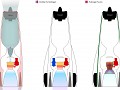
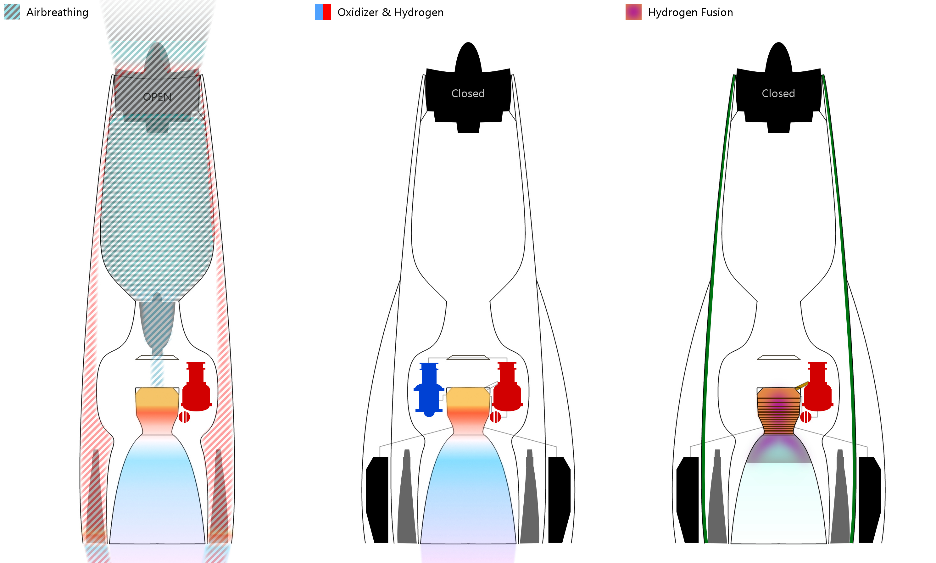
Air breathing:
Air and goes through a series of heat-exchangers which cool it down from over 1000C to minus 150C, after which the air goes through a turbo compressor and is mixed with the fuel in the pre-burner.
Alongside this a hot air stream is mixed with Liquid Hydrogen fuel in the ram-jet burners.
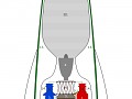
Oxidizer and hydrogen closed cycle:
Liquid Oxygen and Liquid Hydrogen are mixed in preburners and hot gases are pumped through the main gas manifolds to the combustion chamber.
Hydrogen fusion:
Liquid Hydrogen is injected directly into the main combustion chamber where magnetic coils compress and ionize the liquid to create a plasma that is ejected through the magnetized nozzle.
Note that radiation shields are necessary to protect the ship and crew from radiation. For this reason Hydrogen fusion is not used while in-atmosphere and near spacestations/other ships.