![]()
Due to the simplicity of the bomb weapons, this tutorial is the best way to start of anyone interested in making new content from scratch.
Note: This will be a quite long tutorial, because it will try to illustrate every step in the weapon making.
Future modeling tutorials may not be detailed as this one, so that mean this tutorial is one is really the best for complete beginners
The bomb that will be done is the: FAB-500-M62
Is a simple unguided drop bomb with a 500kg explosive warhead.
This weapon was already added to the in the report 034:
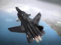
Here is how it will look like in the game by the end of this tutorial:
![]()
When making a real weapon, sometimes can be hard to find good references, for example like weapon information or pictures.
For pictures, is always best to use and orthographic view from the sides, but whenever that is not possible use the image with the least perspective distortion.
Like this:
This image that will be used as reference that can be found in here:
Airwar.ru
If you have this kind of picture, then for modeling you only need to know more the exact length of the bomb.
![]()
The first step is to crop the image. It needs to be exact on the length since it will be the dimension that will be used for measuring.
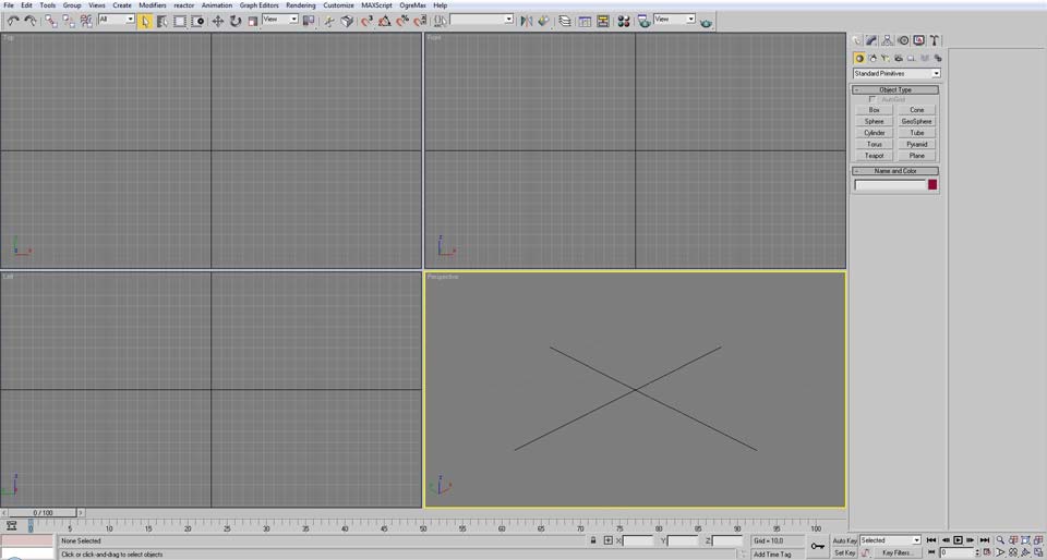
Then the next step is opening the 3d max
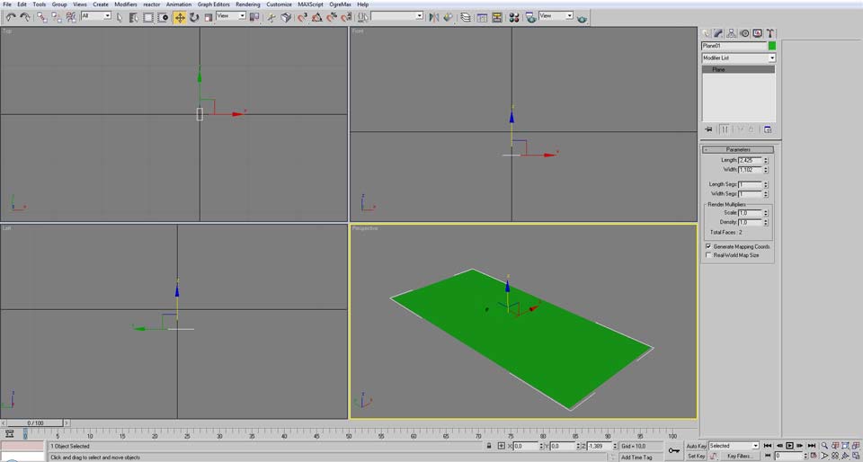
Then create a planar object to be applied the image, the size of the plane must be exact to the desired size.
So while we know the length of the bomb is 2,425m, we don’t know that will be the width for the image.
But because it is scaled proportionally, if we know 332 pixels means 2,425m, then 151 pixeis will be ~1,103m
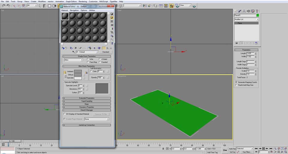
After creating the plane with the desired size, the next step is to apply the reference image, for that press M to open the material editor.
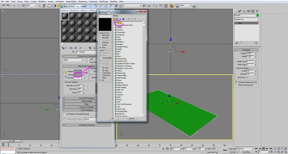
Then we select any of those balls and click in the small square next to the diffuse and chose “Bitmap”

After that it will open a window to find the desired texture. After selecting it, the texture name will be displayed in the highlighted zone, what button call also be used to select the texture.
To apply the texture to the plane click on the third button counting the left in the array that is placed just below the spheres. The one that says “Assign material to selection”.
In case the texture does not appear displayed in the viewport, activate the button in the same array that is a cube with blue checker that says “Show map in Viewport”

After applying the texture, the reference image is not properly orientated. To fix it, go to the “Modify” tab and open the combo box “Modifier List” and select the “UVW Xform”
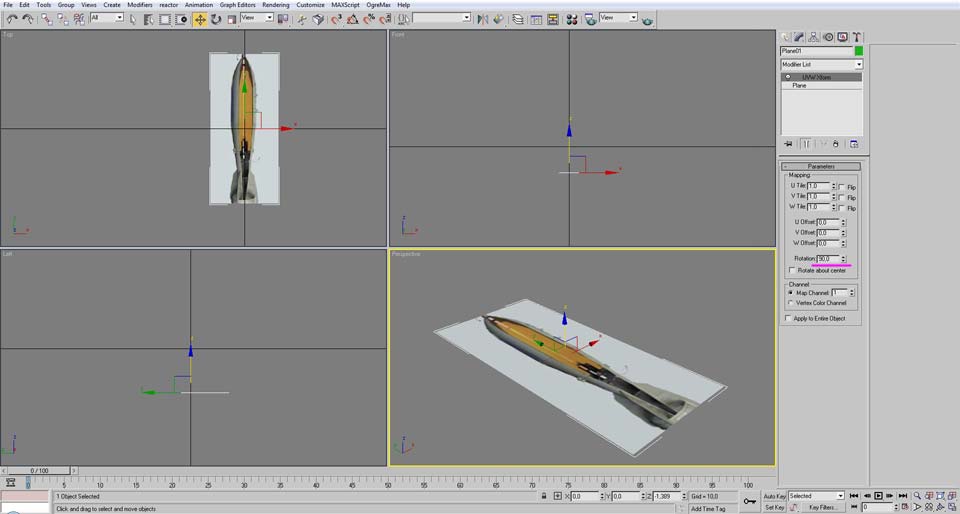
Just apply a 90 degree rotation so the front of the bomb be faced to the positive Y.
![]()
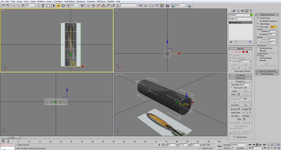
Now that the reference map is placed, the next phase is to model the actual bomb
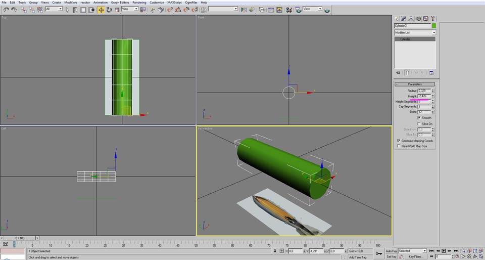
Start of by creating a cylinder and try to roughly match the volume of the bomb and then add a few height divisions.
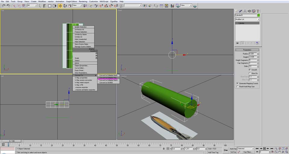
Now convert that cylinder to an “editable poly”, to do that click right button of the mouse with the model selected.
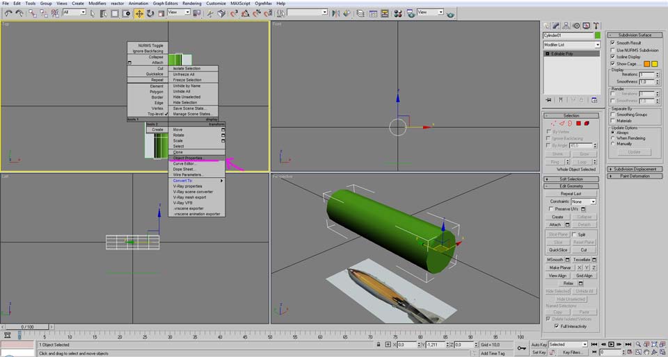
After converting it to a “editable poly”, right click again and open the “Object Properties”.
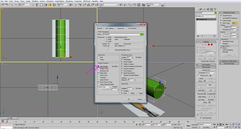
Activate “See-though” option and press ok.
Now the model is somewhat transparent, making it to see the reference image behind it
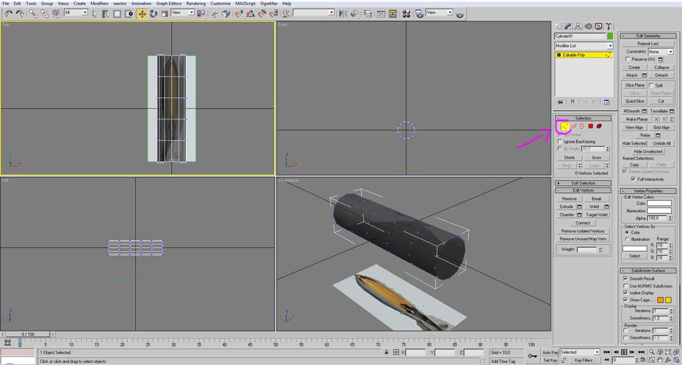
Go to the “modify” and select “vertices” selection. Is time to adjust the vertices to the exact shape of the bomb
For this there are multiple approaches and the method to reach de desired shape largely depends of the intended result.
Anyone should use the method they most see fit. For the sake of explaining a simple way for the most inexperienced it was selected this one.
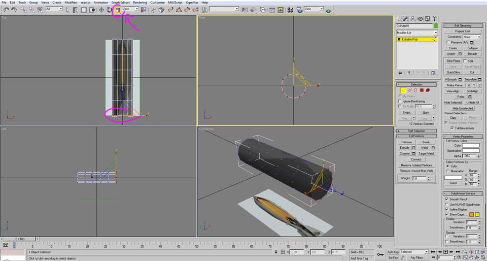
Fist select a horizontal array of vertices (viewed from the top view), then select the scale button.
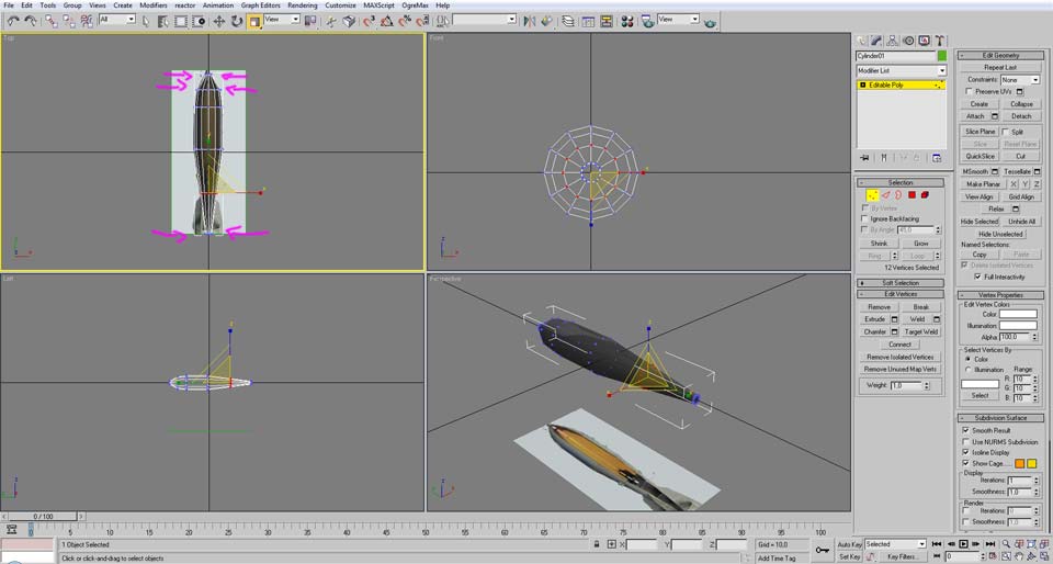
Then scale uniformly to match the shape of the bomb. Repeat the process to all other array of vertices. Also move them up or down if needed.

In case you require to add more sub divisions, a way to add them for this type of model is selecting the “edge” button.

Activate the button “Window/Crossing” that makes only selected the elements that fit inside the selection rectangle.
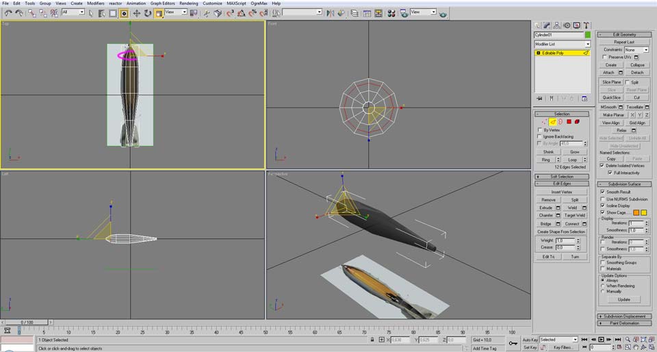
Select a horizontal line near the tip
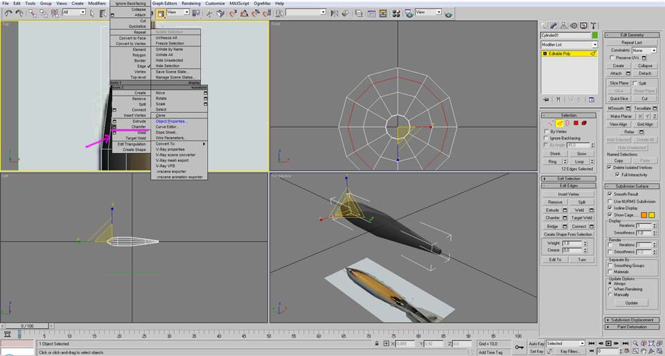
Right mouse button, and select the small button left of the “Chamfer”
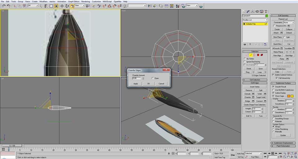
Add the desired amount and then press ok.
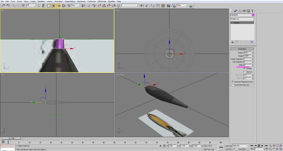
To make the tip of the bomb, create another cylinder, this time it doesn't need so many sides and no additional height segments.

Convert it to “Editable Poly”

Scale the tip as you did before to the bomb vertices.
Remove the back face because it won’t be seen by selecting the “Face” button, make a selection over it and then press “delete” on the keyboard.
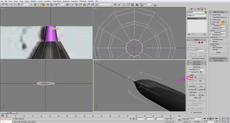
Then select again the bomb model a click in the “Attach” button followed by clicking in the tip model.
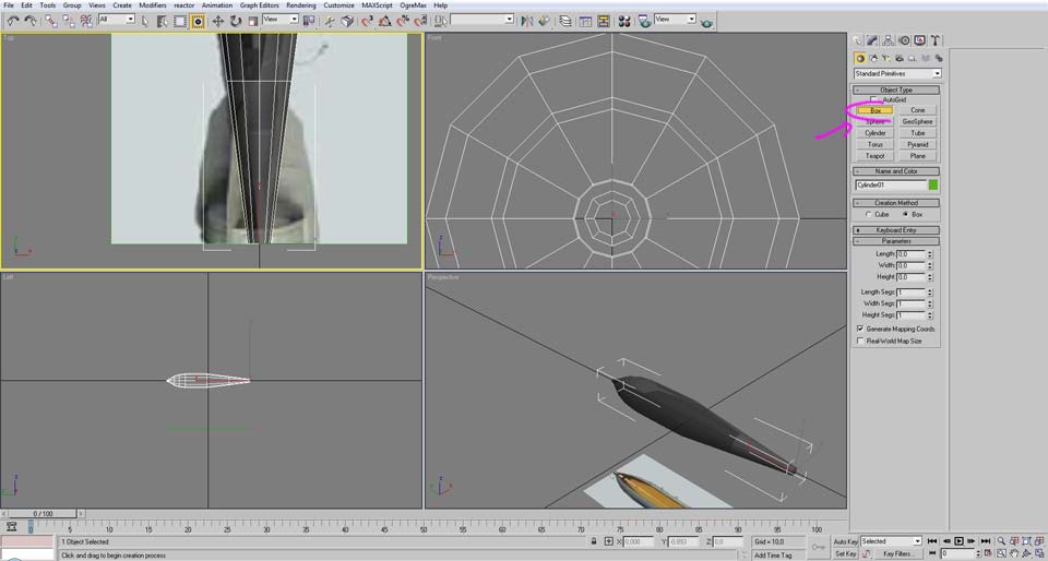
Now it is time to make the stabilizing fins. Click in the “box” button in the create tab.

Create a thin box that roughly matches the shape of the stabilizing fin of the bomb.
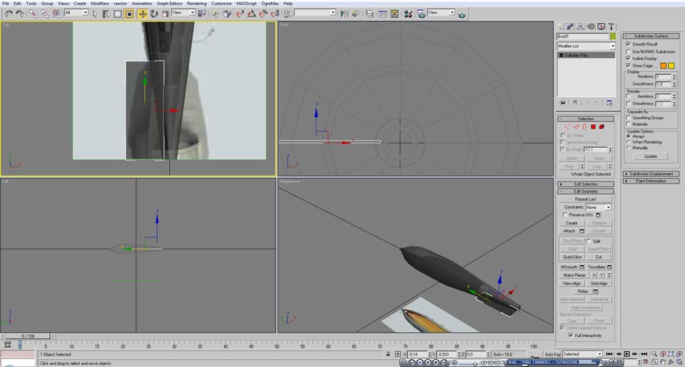
Then convert it o editable poly and make it “see-through”.
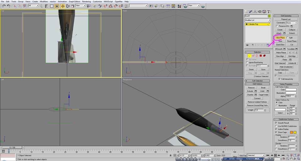
With the vertices select button active click in the “slice-plane”.

Click the button “Select and rotate” and “angle snap toggle”
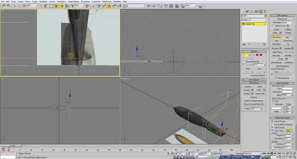
Adjust the angle of the slice plane to make horizontal divisions (viewed from the top view)
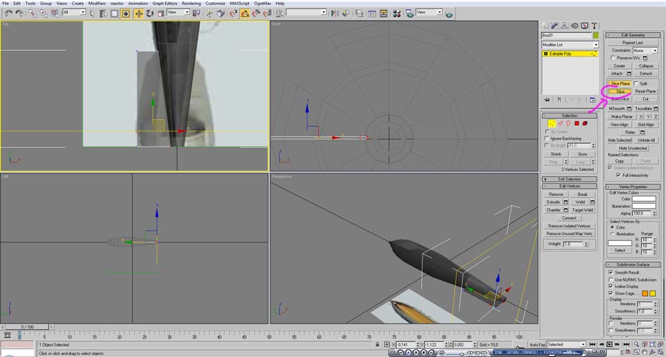
Click the “Slice” button to apply that division.

Do the same above and turn off the “slice plane” and start moving the verities to fit the shape

Use the scale to thin it ever further in the outside tips
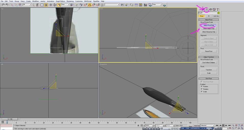
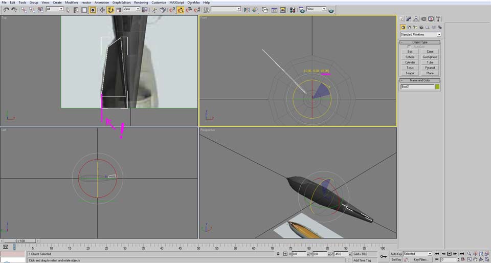
Then go to the “Hierarchy” tab and select “affect pivot only”
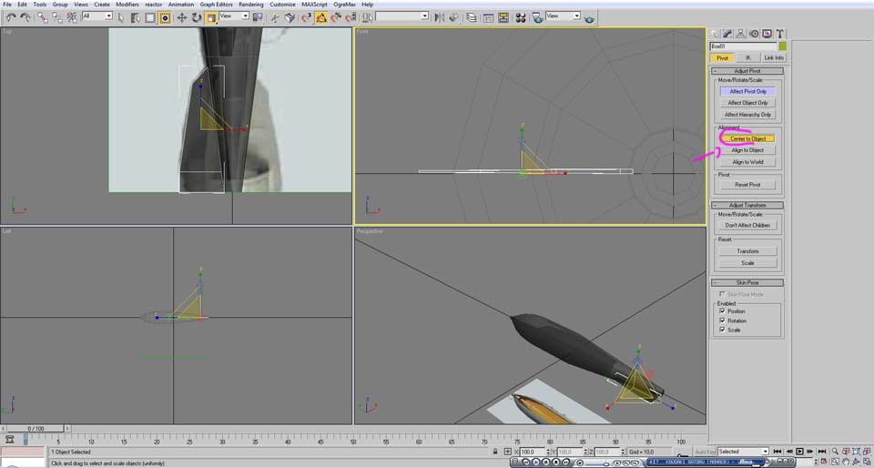
Click in “center to object”.

Change the Z position to 0.
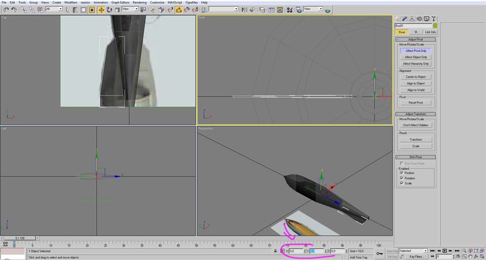
Then the copy the X and Y positions of the bomb to the fin.
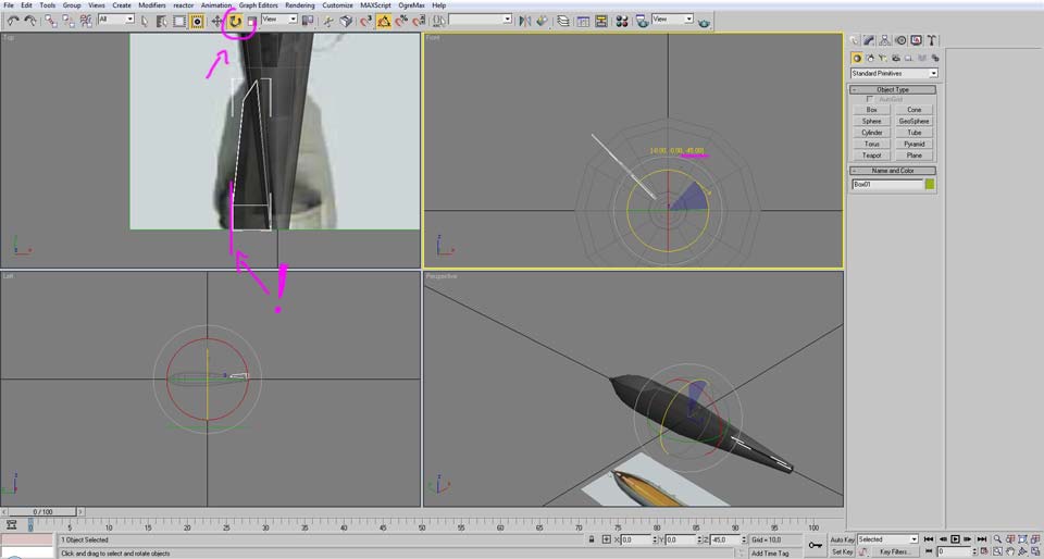
Rotate 45 degrees and now you’ll see something important. We made the fin to the exact shape of the reference image, however in the reference image the fins are in an angle, so we have to add additional size to really match the size in the same angle.
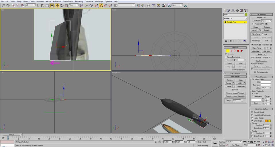
For that we need to move the vertices a little bit to the left, you may need to check several times to see if the shape is correct.
Now we found the correct size. As you see in the same angle the fin matches exactly the reference image.
Now move back to the original angle.

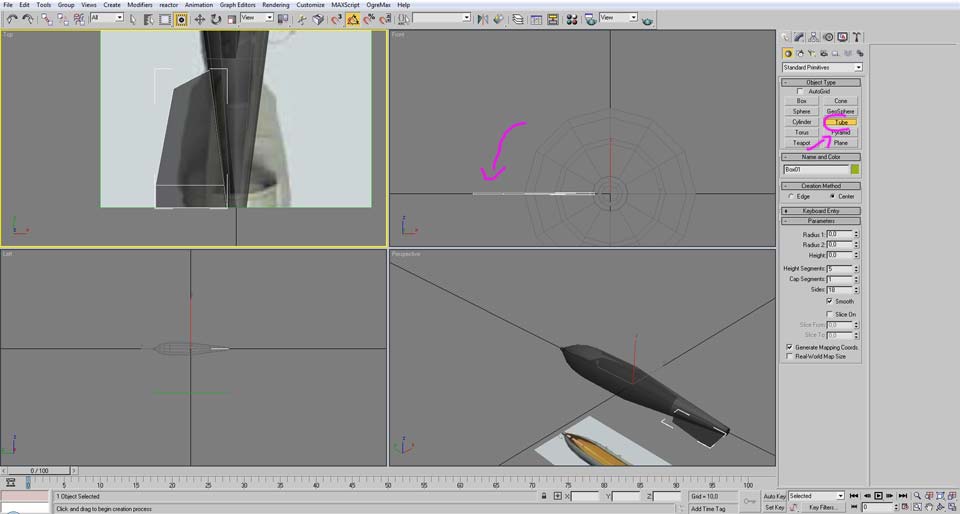
Next is to create the cylindrical fin around the end tip. Create a tube as thin as possible with the same sides as the bomb shape was initially created.
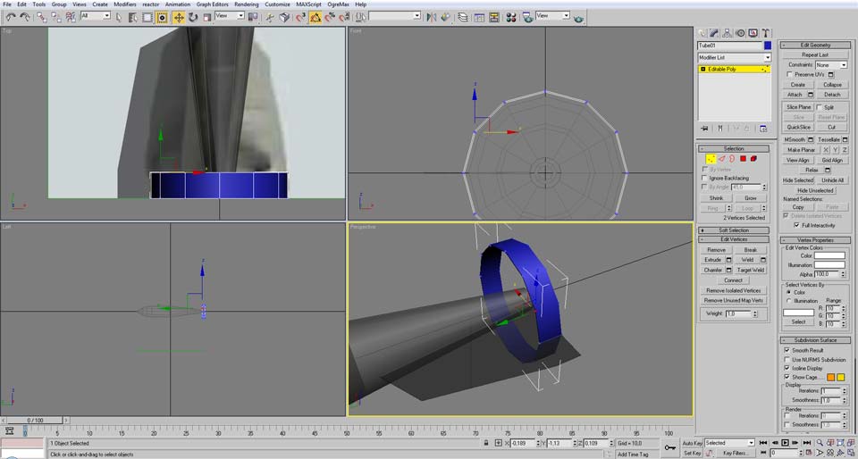
Now convert to an editable poly and select the 2 vertices of the front end of the fins for each side.
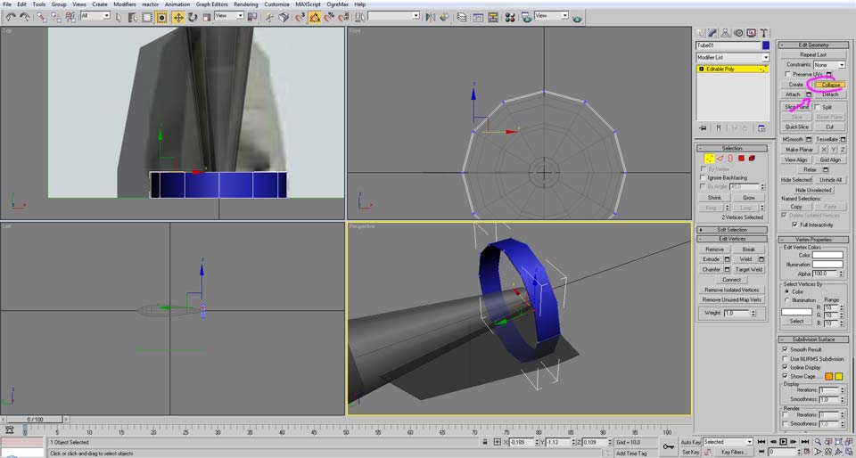
Having the vertices selected click in the collapse button.
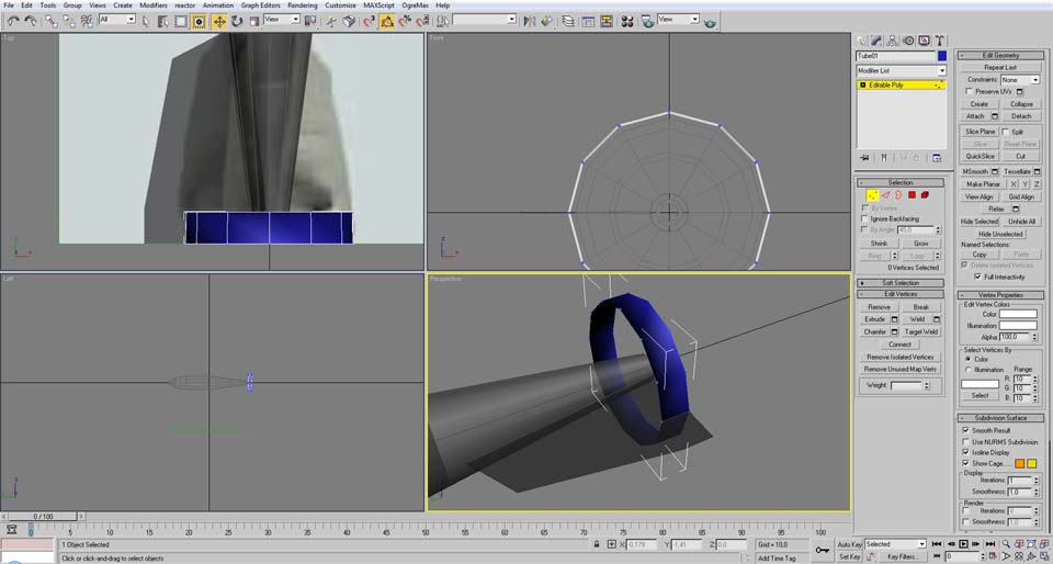
Notice the shape is now a bit strange.
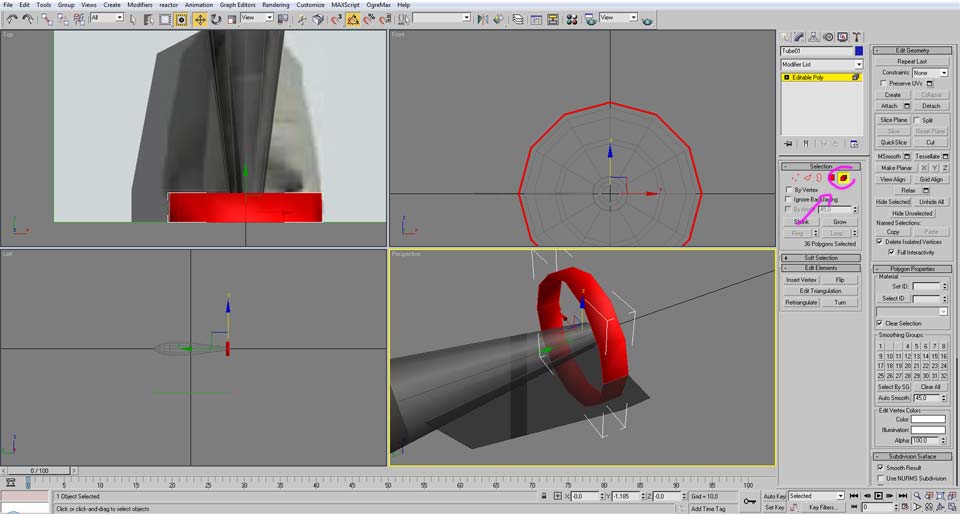
To fix this select the “element” button and select the whole mesh.
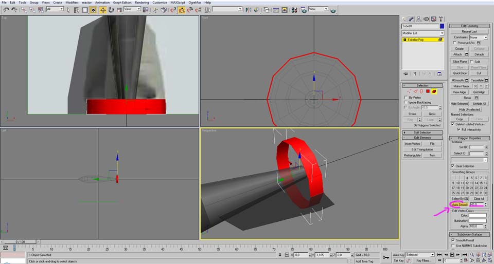
Then click in the auto smooth button.

No select back the bomb model and “attach” the cylindrical fin.
And this is all what we need to model for now, the next part of the tutorial will be explaining the UV Mapping


This was very useful! thank you!
I absolutely don't know this tool thought I 've used stuffs like AutoCad and SolidWorks years ago. Is it hard to learn from this ?
Looks like 3DS Max. Not THAT hard to get into but costs a LOT.