Tutorial written by Aavenr
Mirrored here for archival purposes. Note this is an unofficial tutorial the official Remedy tutorials are located here.
“Backface Culling and Room Modelling”
By Aavenr
Note: some of the following stuff is very theoretical and since it isn’t covered in detail on the official tutorials it was pretty hard to figure out. There may be some minor inaccuracies lying around but I am very confident I’ve gotten the most of it right.
Speed es essential in modern, graphics intensive games and as such developers have to come up with efficient ideas and approaches in order to maximize system resources and get the most performance wise solution. A great number of these methods center around the idea of avoiding having to draw things in game that the player can’t actually see. One of such methods is the backface culling feature employed in the Max FX technology.
Backface Culling Basics
The backface culling technique is one way the Max FX engine optimizes the scene so that unnecessary polygons are not drawn. It basically works this way: First, let’s assume all the polygons are dual sided initially and therefore can be fully seen from the inside of the mesh as well as from an outside point of view. The engine always renders only the polygons that are supposedly visible through the view frustum but at the beginning it can’t distinguish between polygons that are facing inwards from the ones facing outwards and therefore it can’t tell if some which poly is blocking another poly in order to avoid drawing the blocked poly. This causes situations in which the polys are in the view frustum (remember the view frustum isn’t limited by any geometry) but still are not visible to the player and there is no point in drawing them. Here’s an example:
Imagine the player is looking at a square block. The block is made up of 6 polygons (one for each side). Now, each polygon has two ‘faces’ (we are assuming it’s dual sided by default so I can explain this whole thing better), one that’s looking inwards and one that’s looking outwards. This means the block is composed of 12 faces.
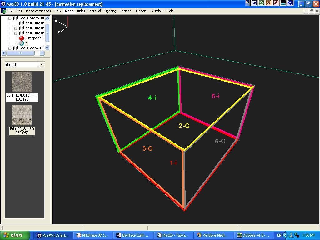
Here you can see what I am talking about. On the picture, each polygon has been assigned a certain number and its edges have been painted with the same color as the poly’s number. Edges with two colored lines mean that to polygons are sharing the same edge. I have also added a capital ‘o’ (O) to indicate I am referring to the outward face and an ‘i’ (i) to indicate the inward face. So on the picture ‘1-i’ refers to the bottom poly’s inward face while polygon ‘2-O’ refers to the top poly’s outward face.
So at the beginning the engine draws the faces it thinks the player can see which are: ‘1-i’,’2-O’, ‘3-O’, ‘4-i’, ‘5-i’, and ‘6-O’. At the same time the engine avoids drawing the other 6 faces which I didn’t name because it knows the player can’t see them. At this point there is no backface culling and the player’s field of vision tells the engine the engine there are only 6 faces visible. It is not taking into account that faces ‘2-O’, ‘3-O’ and ‘6-0’ block or overshadow faces ‘1-i’, ‘4-i’ and ‘5-i’ respectively (it’s hard to tell on the picture because it shows the block in wireframe mode and without any texture applied) and 3 faces would be rendered unnecessarily. So how does the engine realize that 3 polygons are overshadowing the other 3? That’s where the clever part begins, read on.
Single Sided Polygons
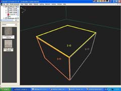
The MaxED modelling philosophy forces the level designer to create objects that have only one orientation at a given time which can be inwards or outwards and hence the name ‘backface culling’. Room meshes are always facing inwards while anything inside them faces outwards. This works because using this modelling philosophy (which I will cover into more detail soon) the player can’t actually see both sides of a mesh at a given time. So, going back to the example, the engine knows the faces have actually only one orientation and therefore the ‘1-i’, ‘4-i’ and ‘5-i’ faces won’t be even considered into the final scene. Picture 2 shows how the block looks when backface culling is enabled as only the outward facing faces (‘2-O’, ‘3-O’, ‘6-0’) are drawn.
Please note that whenever your turn the dual sided property on for a certain material, you are effectively nullifying the backface culling feature for any mesh textured with that material. If you did this with the example block the scene would end up looking just like picture 1 shows (on textured mode you wouldn’t see the ‘1-i’, ‘4-i’ and ‘5-i’ faces but they would still be rendered, eating up system resources unnecessarily).
Room Modelling Principles
The modelling philosophy I referred to earlier in this article is based on the aforementioned ‘single sided polygon’ approach and forces the level designer to adjust his mindset (especially anyone who have has worked with other game editors in the past) and change the way he constructs the level, particularly the ‘top level’ meshes that make up the ‘rooms’. There are instances when some dual sided meshes are necessary (meshes with alpha blended materials mainly) but you never use a dual sided mesh as part of a room’s geometry.
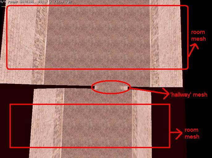
Because every mesh can only have one orientation it is fundamental to apply what I like to call the ‘room-hallway-room’ principle. This structure, if you will, is the one applied on Remedy’s official “Creating your first level” tutorial in which you make a room mesh, union it with a corridor/hallway mesh and then with another room mesh. This doesn’t have to be taken literally. For instance you could have a room mesh, a doorframe mesh that represents the hallway and then another room mesh. You may also have a window frame as the ‘hallway’ component instead of a doorframe. Always keep in mind that parts of a room that in an editor like WorldCraft would be made of ‘meshes’ in MaxED is always empty space. The thickness of a wall or a roof it’s not determined by how thick a mesh is as in WorldCraft but by how much you space the different room meshes.
The ‘room’-hallway-‘room’ principle is meant to be used when creating ‘top level geometry’ by which I mean the meshes that make up the ‘rooms’ and that contain the wall, floor and roof polygons. The principle is crucial because it is the only way you can merge the different room meshes into one single mesh that will be split by exits into different ‘rooms’.
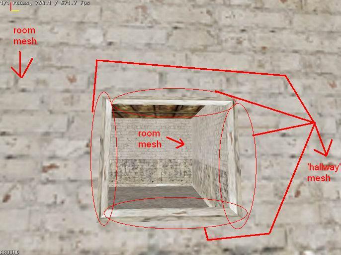
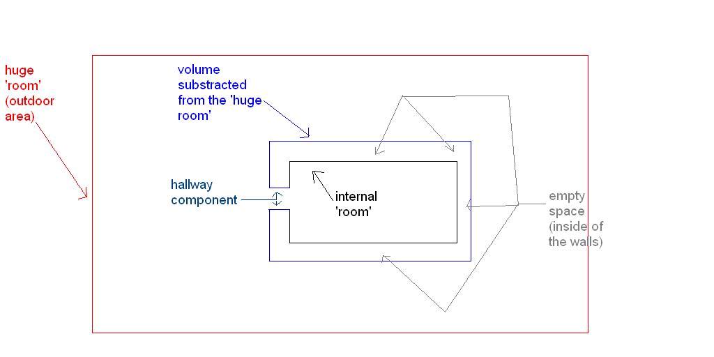
Outside areas represent an excellent example of how the how the ‘room’modelling principle’ must be applied in all circumstances. In MaxED if you want do an ‘outdoor’ area whith a building the player can go in you will have to model it by means of the ‘room-hallway-room’ principle. You will first have to start by making a huge ‘room’ that will be the actual ‘outside’ area. Now let’s say you want the buildings external walls and roof to be 0.5 meters thick. In order to accommodate the ‘internal architecture’ of the building you would have to substract a volume from that ‘room’ that is 0.5 meters wider/longer/taller than the area you want the inside of the building to occupy. Remember, the thickness of the walls depend on how you space the different rooms (the outside ‘huge room’ and the ‘rooms’ on the inside of the building). Afterwards you will have to add the ‘hallway’ component where you want the building’s entrance to be. Picture 5 should make it all easier to understand (make sure it is set to actual size when you view it or it can be a bit confusing).
After reading this I hope you have grasped a bigger picture of how the Max FX works and more importantly, know how to adapt yourself to the technology adjust your way of thinking when working with MaxED.