The requirements
Let's take a look at the second chapter, where we defined the requirement that each module "must be attachable to their neighbors from six edges". So when there are modules in adjacent hexes, both must create a connector against the common tile edge. No connectors are needed against empty hexes.
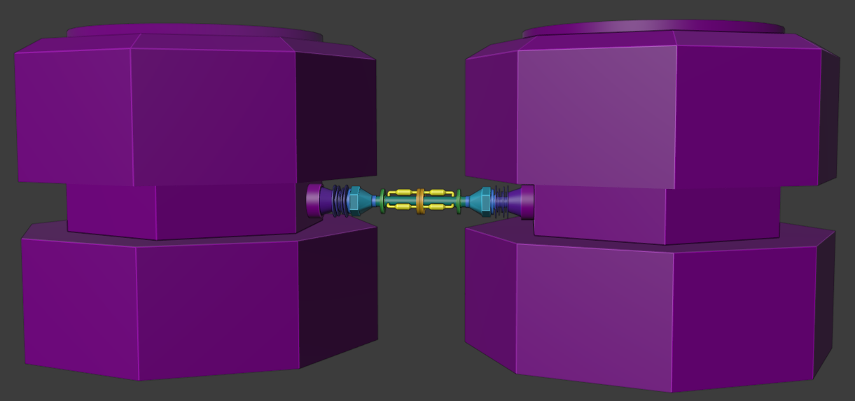
The image below shows three connected modules with their associated connectors.
Connectors are attached to modules from their bases and joined together from their tips.
The "requirements"
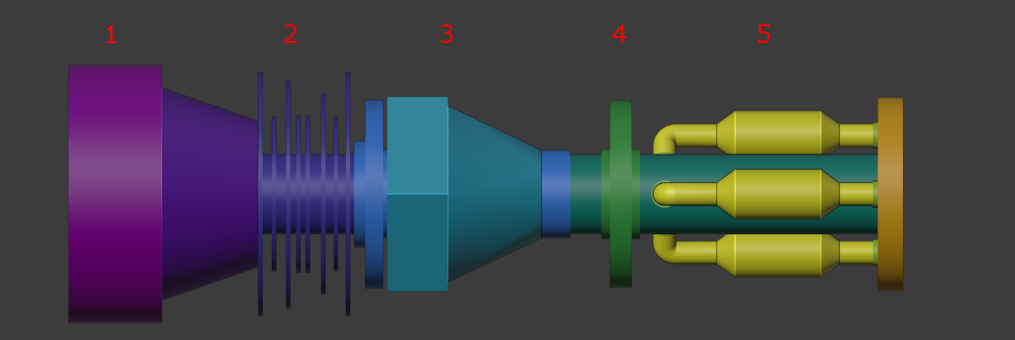
In order to have ideas for modelling, one needs a story. In this case a series of fictional pseudo-scientific rules. Completely useless from the technical standpoint, but here it goes anyway:
- Connectors are attached to modules with a sturdy base (1). Even the strongest hit can't detach them.
- As connectors must stand constant collisions, some flexibility is needed. Set of loose plates (2) will dampen hits. They are fastened with a big screw (3), that adjusts the maximum flexibility. The front plate (4) prevents the connector from budging too much.
- In addition to keeping the modules together, connectors must also transport energy and information. For this, there are three separate pipes (5): one is for energy, one is for common control interface while one is reserved for future expansions as new module types will be added regularly. For easier maintenance, they are exposed near the tip.
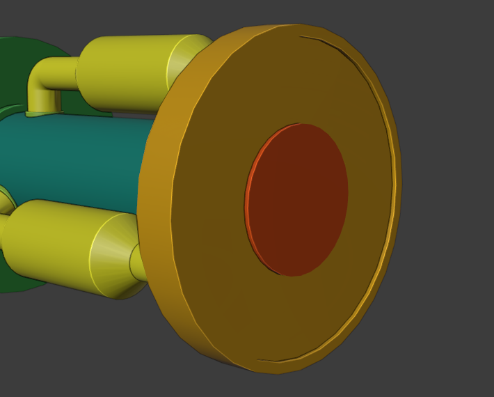
- At the very tip, there is a magnet that keeps the connectors attached to each other (colored red in the image below). Bolts might be a more practical solution, but magnets are cheaper: when a module is detached from the ship, its connectors and magnets lose their charge, and let go from others without causing further damage.
Modelling
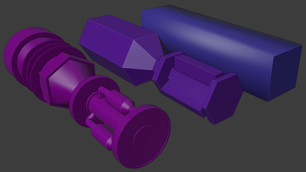
The modelling process is a little different from the base module. This time I made the hi-poly model first, and then created medium and low poly models that encapsulate the most detailed version as tight as possible.
I first modelled the core, attachment parts and stoppers as one mesh. Basically it was all just extruding, scaling and insetting. Although being a one object, the parts should look separated; I assigned them with different color IDs, so it is easy to give a unique material for all in Substance. As the game mostly uses top-down view, the texture seams are placed beneath the model (notice the red line).
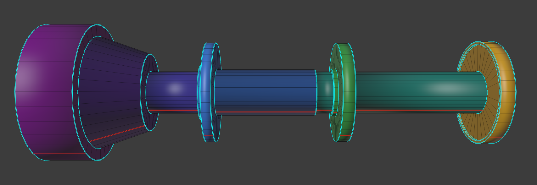
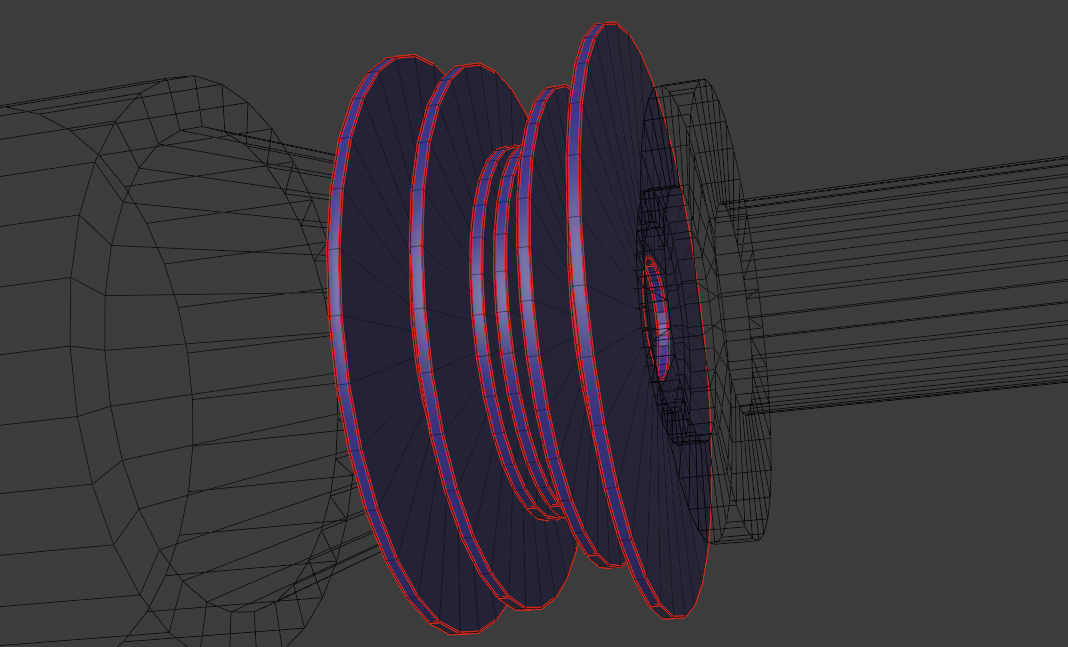
Plate models are started from a circle ("Add" -> "Mesh" -> "Circle" in object mode). I first filled the circle by selecting all edges in edit mode and pressing F. The hole in the middle is done by insetting the outer edge and deleting the center face. Finally I extruded the remaining faces to give the plate some depth. Texture seams are placed on each sharp edge as well as in the bottom.
After one plate was ready, I duplicated them by selecting the object and pressing shift + D. This copies the whole mesh and lets you edit objects individually. Size variation is done by simply scaling the outer surface.
The large screw I started from a hexagonal cylinder after which I created a circle for the front part with more segments. I joined the objects and created connecting faces by selecting edges and clicking "Edge" -> "Bridge Edge Loops".
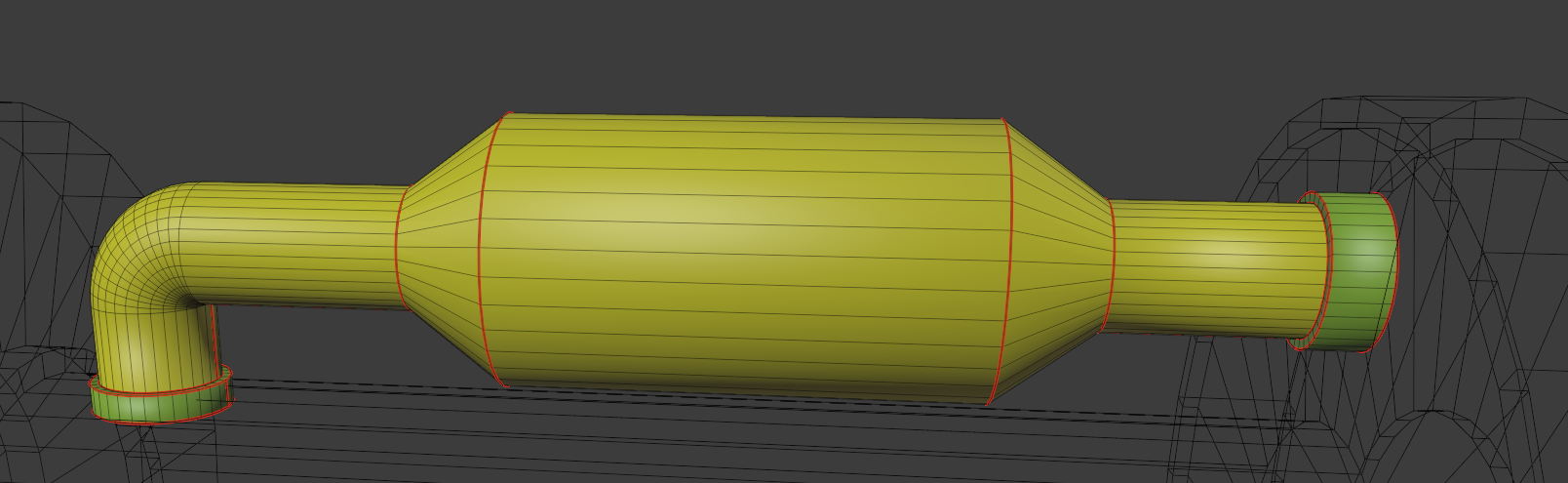
Pipes are just cylinders with varying thickness (extrude + scale). For the bend I used the spin-tool. Attachment parts are textured separately and thus assigned with a green material. I modelled one pipe and used the array modifier to make three copies of it around the connector.
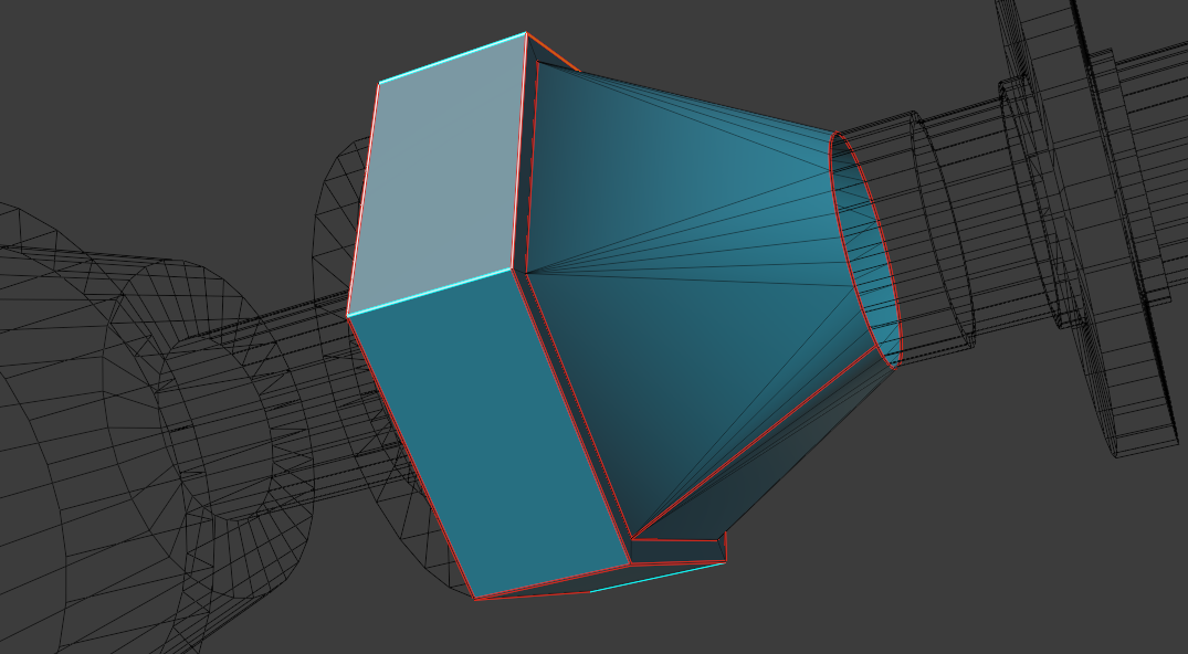
The details are mostly unseen during the gameplay, so I made two simplified models. Medium LOD model in the middle roughly follows the hi-poly model’s form. It is just an extruded/scaled hex cylinder, where the pipe-parts are extruded individually (select faces -> alt + E -> "Extrude Individual Faces"). The lo-poly version at the back is merely a box, but good enough for distant views.
Texturing
Connector's surface should look worn and damaged; that it has taken collisions all over and that it is made to stand them; whose paint has lost its color; scratches, bumps and cannon hits all over. Settings and workflow are pretty much identical to the base module except for the emission channel that is not needed. 1 cm baking distance is used for the hi-poly model and 7 cm for the other two. I took "Steel Painted Scraped Green" as base material and I reduced the paint color saturation to almost zero.
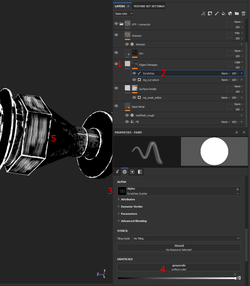
As the big central screw needs to be fastened regularly, there shouldn't be much paint left on it. I scraped the paint off manually by the following steps:
- (1) Alt + click at the "Edges Damages" -layer in order to show the mask only. White parts will be filtered out from the base paint.
- (2) Right click "Edge Damages" -filter and select "Add paint". This will add a new mask above the generated mask "mg_curvature", so further details can be manually painted onto it. I named the mask "Scratches".
- (3) Select the created mask, click "Alpha" and pick "Scratches Scatter"-brush from the menu. That one seems to be the best brush for directional scratches.
- (4) Set Grayscale to 1.0. This way we will be painting max value (white) onto the previous filter and thus scrape off the paint.
- (5) Paint/scrape by dragging an alpha brush around the model.
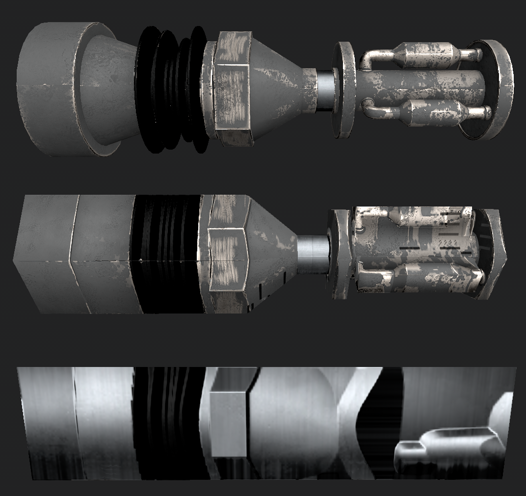
Plates must be oiled in order to be loose and easily rolled. I used rubber material with a bumpy height map, roughness set to minimum, metallic to maximum. This gives a greasy and slimy appearance. Magnet and moving parts are constantly collided and chafed, so they are missing rust and paint completely.
Textured LOD models are shown below. Low-poly model's details are naturally quite obfuscated, but otherwise I see no remarkable bleeding or artifacts. Low-poly version could utilize alpha-clipping in order to better match the shape of the high-poly model, but since black already blends with the game's space background, there's hardly any need for it. I'll cover the types of transparency (both alpha blending and clipping) in the following chapters.
Unity
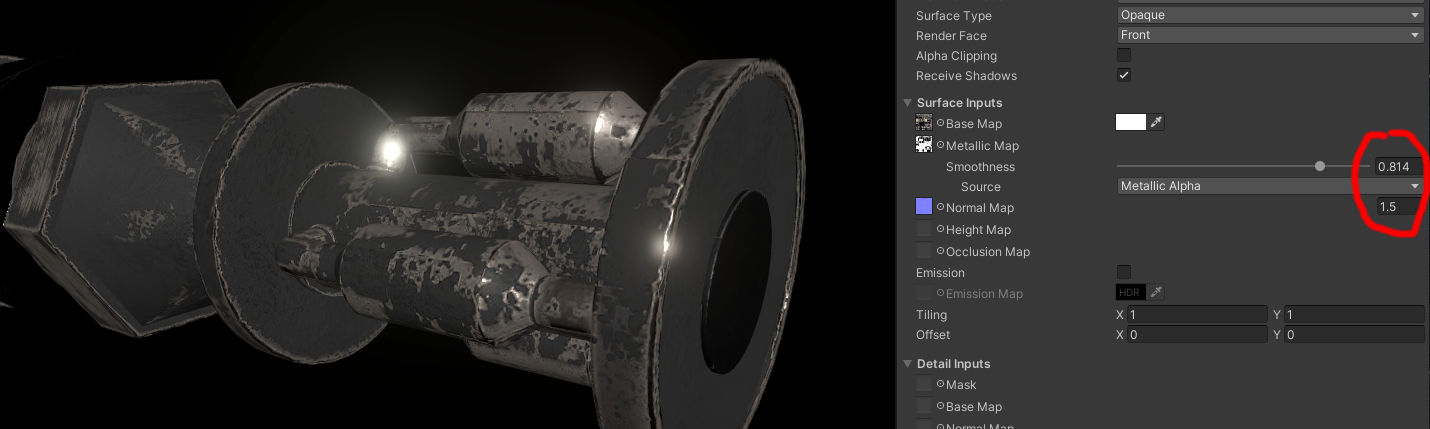
Models and textures are imported and materials created as described in the previous chapter. I increased material smoothness to ~0.8 and normal map power to 1.5 in order to emphasize the rough, metallic look.
I encapsulated the connector inside a two-dimensional box collider (see the green boxes) and then created a prefab from which the associated module-object is able to create connector instances. The image below shows a module with connectors instantiated on all six sides. Note that hardly half of the connectors will actually be visible from above.
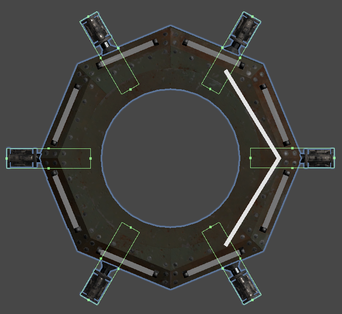
All colliders are automatically combined inside the nearest rigid body, and thus contribute to the collisions. Rigid body may be the ship (when a module is attached) or the detached module itself. Connectors are not removed from the detached modules.
Performance
There are going to be a lot of connectors visible at once, and as they are very tiny and only a small portion of them can be seen, the least detailed version should be primarily used. Level of detail usage is pretty much similar to the last chapter, but there are some issues worth mentioning.
After publishing the previous chapter I spent quite a while trying to figure out why my LODs got suddenly messed up and why only the high-poly versions were visible. I changed scalings and rotations, reimported models and practiced all sorts of magic, but in the end there was only one additional click I had to do. So fellow Unity-users, a beginner's tip: remember to push the "LOD Group" -object's "Recalculate Bounds" -button whenever it is enabled.
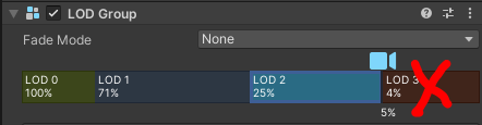
Secondly, some module parts disappeared completely when the camera raised far enough (LOD group's culled-state was reached). I ended up removing the cull-states (the rightmost part in LOD group -component) altogether as it serves no purpose in this game.
All the LOD problems initiated from tiny changes I did while writing the previous post. Such glitches may go unnoticed since it is hard to tell which LOD level is visible at the moment. Unity has no proper built-in debugging tool for LODs, so I quickly wrote my own; just add it into the game object with LOD Group, and it shows the current LOD level on top of the object. For now it assumes that LOD objects are direct children of the LOD group object, and each LOD model contains MeshRenderer. So not a robust solution, but suits my purposes and is easily extendable.
public class LodDebugger : MonoBehaviour {

  private string ResolveCurrentLod() {
    foreach (Transform child in transform) {
      var renderer = child.GetComponent<Renderer>();
      if (renderer != null && renderer.isVisible) {
        return child.name;
      }
    }
    return "none";
  }

  private void OnGUI() {
    var currentLod = ResolveCurrentLod();
    var position =
      Camera.main.WorldToScreenPoint(gameObject.transform.position);
    var textSize =
      GUI.skin.label.CalcSize(new GUIContent(currentLod));
    var textRect = new Rect(
      position.x - textSize.x * .5f,
      Screen.height - position.y - textSize.y * .5f,
      textSize.x, textSize.y);
    GUI.Label(textRect, currentLod);
  }

}
LODs take care of vertex count issues but as there are dozens of modules visible at once, models and materials should be batched properly in order to avoid constant state changes.
I disabled both "SRP Batcher" and "Dynamic Batching" from the render pipeline assets and ended up using GPU instancing (check "Enable GPU Instancing" from all recurring materials as shown below). Instancing seems to be the most suitable solution for the modules and connectors since it "is useful for drawing objects such as buildings, trees, grass, or other things that appear repeatedly in a Scene". In other words: if there are lots of identical meshes and relatively few materials. And it does indeed drop batch count significantly.
Below are the batching values for the ship with 100 plus modules when using the highest quality settings. All the module-specific parts as well as battle arena background are included.
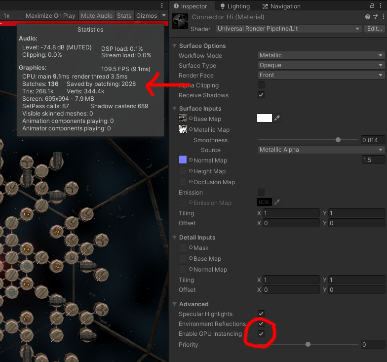
So far the benchmarking on slow laptops has given promising results: even rather cheap laptops with integrated GPU manage to run the game well over 60 frames per second.
Problems/lessons learned/future enhancements
- I spent way too much time while modelling the hi-poly details; this post is most likely the only place where the model is ever seen. Let's take it as a modelling practice.
- But I could still replace the plates with a spring...
- I'm assigning too many materials in Blender. I usually end up using only a few of them in Substance.
The next chapters
There will be a change in the plans: instead of writing one post per module, I will be grouping modules with similar workflow together. The reason is that I found plenty of repetition while gathering content for the following chapters. The change leads to fewer and longer posts, but hopefully adds more tutorial value.
Thank you for reading. In the next chapter, we will be doing transparent surfaces.