Originally posted here: Stargatecommand16659.yuku.com
Created by: MaLuS
Mirrored here for archival purposes
Note this tutorial exceeds Moddb's maximum article length. This is part two.
Brush Power Tools
Even with DEdit’s primitives and its vertex-by-vertex brush layout tool, you still can’t create all of the brushes you want in a single step. DEdit has four main tools for changing the actual shape of a brush: Hollowing, Carving, Splitting and Geometry Mode.
The reason that these tools are in a section called “Power Tools” is because that’s what they are. While they are very useful tools, they are also very effective for destroying brushes, making your levels slower to process and slower to run, and making bad designs worse. As in carpentry, think twice before you cut. Be sure of what you will get before using these tools.
Using hollowing, you can empty the inside of a brush, like hollowing out a pumpkin. For a demonstration of how to use this technique, you can very quickly build a box around your entire level to contain it for processing.
First, raise the marker about 128 units above the tops of your columns. Then, zoom out your Top view until you can see all of your level’s brushes and a little space around it. Re-select the texture you used for the floor of the level, since the texture of your pillars and supports is a bit too dark for easy viewing.
Draw a square brush that surrounds the whole level in the top view and make it 1024 units tall. That’ll make it large enough to contain the whole level with some space left over. Now, with the big new brush (and nothing else) selected, select Hollow from the Brush menu. When prompted, enter 64 for the new brush thickness. This is the thickness of the walls of the brush, which will be created around the brush. Then the original brush is deleted.
You’re probably annoyed that you’ve been taught to create rooms using the slower method of laying out each of your wall brushes and ceilings by hand instead of just creating and hollowing cubes. However, if you look at the created brushes, you’ll see that DEdit created brushes whose edges are beveled instead of straight. This is to fit them together neatly with the minimum number of faces visible, although in some cases hollowing can drive up the number of faces on your brushes, leading to higher polygon counts inside your game. Also, because of the beveled edges, hollowed rooms must be resized by moving vertices, instead of by scaling whole brushes.
Hollowing can be useful, especially when the bevels fit in with the design of your room, or are in areas that won’t affect the rest of the layout. If you’re using it in an area of the map that you plan on changing a great deal, consider building your brushes by hand instead. It’s usually neater even if it is slower.
Your next tool is carving , also known as CSG Subtraction . It’s similar to hollowing and the two can even be used interchangeably for some purposes. However, as with hollowing, it can often produce unintentional results.
In order to carve a brush, first you need to create the brush to be carved. Next, you need to create a second brush that will serve as a tool to carve with . As you may guess from the name of the operation, the volume of the second brush will be subtracted from the volume of the first brush.
As an example, you can bevel an edge off of the top of your two pillars to give them a little more of an interesting look. Select one of your triangular supports. Copy ( CTRL+C ) and Alternate Paste ( CTRL+ALT+V ) it, then move ( M) it so that it overlaps the outside edge of the support.
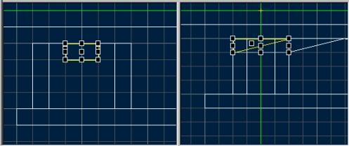
Resize the copied support so that its edge is a 45-degree slope in the Front view, then resize it in the top view so that it overhangs the north and south edges of the pillar a little. You should get a brush that looks like this:
The purpose of the overhang is to make sure that the brush cleanly carves the surface of the pillar. It’s not necessary, but it’s a good idea. DEdit may occasionally create a bad edge or face when using carving, and overhanging a little helps to minimize the chances of this. If it does happen to you, use undo to back up and then try resizing your carving brush to overhang the area where the problem appeared if it’s possible to do so.
If you can’t overlap the carving brush for some reason, see the section on fixing damaged brushes later in this chapter. It includes techniques that might help you fix any damaged brushes that result. You may also be able to use splitting planes (which you’ll learn about next) to do what’s needed.
Notice that your carving brush only touches the pillar and not any of the other brushes in the level. That’s because carving with a brush cuts its shape out of any other brushes it’s touching. Make sure that your carving brush isn’t touching anything you don’t want to carve. You can select both the column and the carving brush, then use the Hide Inverse command on the Selection menu to hide brushes that are in the way. Then select any brush and use theUnhide Inverse command to bring them all back. Alternately, you can move the carving brush and the brush to be carved to an area of the level that’s open enough to avoid the problem and move them back when you’re done.
Once you have the carving brush in place (make sure only the carving brush is selected), press H or use the Carve command on the Brush menu. Move the carving brush away from the column and look at the result. What you should see is that a new edge has been carved off of the column, leaving a large beveled edge. As with resizing brushes, it’s a good idea to line your carve up so that any new vertices stay on the grid, although this is most often a problem for brushes you plan on doing more to after the carve. If you’re building chunks of rubble, you may not care as much about the results being on the grid.
This technique can be used with more complex shapes as well. If you stick a cylinder-shaped brush into a wall to make a doorway or into a ceiling to make a window, you can create some very complex effects quite quickly. However, as with hollowing, your decisions on how to lay out brushes are very often better than the computer’s, and your cuts are probably going to be neater and easier to understand. The splitting planes tool, your next power tool, is designed with exactly that in mind.
Note: You might want to create some brushes outside the current map and try playing with carving for a little bit to better familiarize yourself with how it tends to cut before moving on. Try more complex carving shapes and carving multiple brushes at once. Be sure to watch the brushes that you get as a result. To more easily view the splits on your brush faces, turn off the textures. Right-click on the Perspective viewport, choose Shade Mode and then clickFlat Polies .
The splitting plane tool is like carving, except that instead of using a full brush to remove a section from other brushes, you use a single plane as a saw to cut brushes into pieces. Although this tool only cuts along a single plane, it’s a very useful and refined device for making complicated brushes for two reasons. First, it doesn’t require the creation of a cutting brush. Second, it allows you to pick the exact position and order of the cuts as they’re being applied instead of letting DEdit make the decisions.
To see the tool in action, select the pillar whose edge hasn’t been beveled off yet. Splitting planes only splits through the brushes that are currently selected, so they can be used even in crowded parts of your level without the problems inherent in carving.
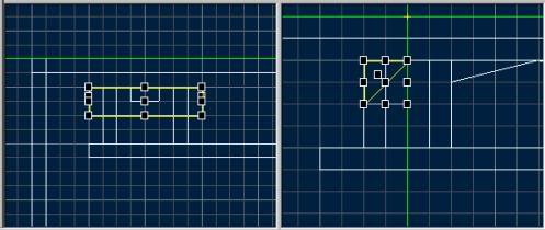
Next, you need to draw a splitting plane that’s located where you want your cut to be. Since we’re trying to be symmetrical with the other side, our cut should cut off the outside corner from two grid lines in at the top to two squares down on the side, a 45-degree angle cut. To define your cutting plane, you do as you’d do if you were starting to create a new brush along the line to be carved: Go to the Front viewport and press SPACE to define a line between the two points where you want the cut:
Make sure you only define two points on the line, since splitting only uses the first segment of the line to split on and will ignore any later segments. Use SPACE to place the first spot, then move the mouse to your second spot and press SPACE again to define the second point.
Note: Splitting occurs along an infinite plane defined by the two points you place. You do not need to ensure that you overlap all selected brushes or make the line the full length of the split you’re creating. Just make sure that the two points you choose are on the exact line that you want.
Once you have your split line defined, press S to perform the split. Your selection will be cleared, and instead of one brush you now have two: a pillar with a beveled edge and a wedge of pillar that’s been cut cleanly off. If you select and delete the wedge, you’ll have a pillar that’s a mirror of the pillar on the opposite side.
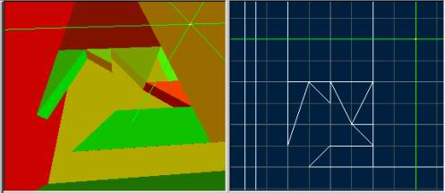
For a more complex case, imagine that you want the floor of your level to float in space. Now, imagine that you want to blow off a corner of the platform to make it appear damaged. What is the best and cleanest way to do it?
First, select the floor brush. Now, go into the top view and center in on the 4 squares in the lower left hand corner of the brush. Once you have a good view of them, split the brush vertically at the edge of the second square in from the left.
Select the smaller of the two resulting brushes (the left-hand one) and split the bottom two squares off so that you have a rectangle above a small square that forms the lower left corner of your floor. What we’re doing is isolating the rest of the brush from the area we’re going to work on. This is important, since one of the things we want to add is a splintered, irregular edge. Always choose carefully where you make your cuts. Otherwise, in this case, the whole floor here would be splintered and irregular which would drive up polygon counts and look ugly.
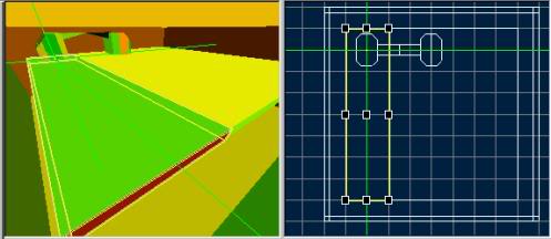
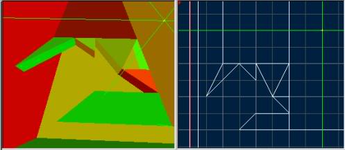
Now, select the square that you created. Zoom in on the square and lower your working grid size in the top viewport to 32 units so you can create smaller cuts. Now, using the splitting tool, carve up the brush and delete any excess bits until you have a nice jagged corner like this one.
You may want to use the flat shade view in your Perspective viewport again to do your carving, since it’ll be easier to select items that way. Note that you can now create a pretty complex shape without destroying the rest of the floor. Imagine what the floor would have looked like if you had used carving instead of splitting.
DEdit’s last brush power tool, which you’ll use to fine-tune the raggedness of your destroyed corner, is called Geometry Mode. Unlike Brush Mode, where each operation works on a whole brush at a time, Geometry Mode works on a single face, edge or vertex of a brush at a time.
Press CTRL+G to switch to Geometry mode. Move your mouse around in the Perspective viewport and watch what happens. What you should see is red highlights around the brush faces as you pass over them. You will also see green highlights on nearby edges and vertices. For the most part, you don’t make normal selections in Geometry mode the way you do in Brush or Object mode. The red highlight is DEdit’s way of indicating where the focus is instead.
In the Top viewport, move the mouse over the end of the triangle on the upper left edge of the jagged area. Get the mouse over the tip of the triangle that juts out of the corner into space. You’ll want to move that point so that the jagged edge sticks out further into space and looks more torn. Press and hold the M key, then click and drag the point of the triangle a grid line to the left.
What you’ve done is move the two vertices that make up the point of the brush over to the right. Something you may also notice is that you actually moved two vertices, not just one. You moved the vertex on the top face and the vertex on the bottom face, which was directly below it in the top view. DEdit knows that since the vertex on top had another vertex directly connected to it that was below it, you probably wanted to move the whole edge. DEdit only makes this assumption when the vertices are both on the same brush and are directly connected by an edge. In order to move vertices that aren’t linked this way in a single step, you have to select them a different way.
The right corner of the triangle you just resized butts up against the corner of another brush. Get that corner in view in the top pane. Then hold down the left mouse button and drag out a rectangle that surrounds that corner. Be careful to only select the one corner, and not any other vertices. When you release the key, you’ll see a yellow dot indicating that the vertex is now selected. If you use the other viewports, you’ll see that all the vertices at that point are selected, whether they’re on the same brush or not.
The nice thing about this is that you can now move all of them as a single unit. Press and hold the S key and drag the yellow dot to the right by one grid space. You should see that both brushes change shape when you do this. It’s important to know what vertices you’ve selected when using this method, since it’s easy to grab the wrong ones. If you have trouble, you can always hide the surrounding brushes to make it easier. Remember, M moves the vertex you click on (and those below it if connected via an edge) while S moves the vertices you have selected.
Now, press U to unselect the vertices you currently have selected. Go back to the triangle that you re-shaped before. Use the same technique to select its tip. However, instead of moving it left/right, you’ll be moving it downwards. Go into the Front viewport. Press the S key to drag the two vertices down three grid lines. In the Perspective view, use the camera to look at the result.
What you’ve done is bend your original brush downwards to make it droop. This is where the real power of Geometry mode comes in: You have the ability to totally re-shape a brush down to its smallest features. You can use Geometry mode to fix brushes when their vertices don’t line up with the grid, to resize irregular objects and to repair all kinds of problems.
One other way to select objects in Geometry Mode is to use the Y key to highlight all the vertices on a single face. Move the mouse over a face so that it’s highlighted, then press Y . What you see is that all the vertices on that face are now selected. This is the method most commonly used in DEdit to skew a brush: you select the face and then use the S key to move it around, skewing the brush.
The last area where Geometry Mode is highly useful is face-by-face texture management. There are cases where applying a single texture to a whole brush won’t get the result you want. For example, perhaps you want to darken the edges of your ragged corner.
In the Perspective viewport, highlight the side of one of your pillars. Next, right-click and choose Select Texture from the context menu. If you now go to the Textures tab, you’ll see that the texture on the pillar is now the active one. Using this tool helps you to quickly grab a texture without needing to know where it’s located in your texture tree.
Move the camera so that you can see the edges of your ragged corner.
Hover the mouse over one of the edge faces of your ragged brushes and press CTRL+T . The highlighted edge now has the dark texture on it. By moving the mouse and camera you can quickly re-texture all of the brushes to the new, dark texture.
Since Geometry mode is such a powerful tool, it also allows you to damage brushes and create objects that the LithTech engine can’t run. DEdit assumes that users in Geometry mode are experts doing things for a reason, so it allows them to do actions that might cause problems because it thinks that is what they want to do. You can probably easily imagine ways to make concave brushes using Geometry mode, but there are more subtle problems you can cause using this mode as well.
Do not use Geometry mode to mirror brushes. If you select a face or group of vertices and drag them so that the brush becomes inverted, the brush will literally turn inside out, with the normals of each face towards the center, resulting in a bad brush when compiled.
Do not twist the faces of a brush. This is a hard concept to demonstrate. Say you have a face that’s rectangular, and you pull one of the vertices straight downwards, as in Fig. A . What results is a twisted face.
Since faces must be totally flat, you have effectively split this one face into two without creating an edge to separate the new faces. To DEdit this will register as a concave brush, and Processor will not be able to properly compile it. Twisted faces are probably the most common kind of Geometry mode problem, and the hardest to spot in many cases. Open the World menu, select Debug and click theFind Concave Brushes command to double-check your work occasionally if you’re working heavily in Geometry mode. If DEdit complains about a brush and you can’t see anything wrong with it, chances are good that you have twisted a face.
You can delete faces and individual vertices, but unless you really, exactly and specifically know what you’re doing, do not do this . More often than not, you’ll create a bad brush. There are tools to do this in the Debug and Specialsubmenus under the World menu for fixing the problems that can result.
Geometry mode is very effective for doing many things that otherwise simply couldn’t be done, but it’s also very easy to do serious damage with it. It’s the most powerful of the power tools, and as such should be used with plenty of care and attention.
Advanced Texturing and Alignment
So far, most of the texturing that you’ve done has been relatively simple, but DEdit supports more intricate texture work as well, both on a brush-by-brush level and on a face-by-face level. You’ve seen how to texture whole brushes, as well as how to texture single faces. You’ve also learned to select a texture off of a face without having to find it in the Textures tab.
Even when you follow all the rules of good brush layout and level design, some textures don’t line up where you want them to be when you first apply them. Either the texture’s edges don’t line up with the edges of the brush, the only texture that has the symbol you want on it is too large, or a crate is rotated off the grid and its textures are not.
This section will show you how to scale, rotate, offset and flip textures. In Brush mode, select the largest piece of the floor under your pillars. Get a good view of the brush in the Perspective viewport, then right-click. In the context menu, select Map Texture Coordinates.
You can use this dialog in either Brush or Geometry mode. In Brush mode, the settings affect all the faces on the brush. In Geometry mode, this same dialog can change each face individually. Instead of selecting the face you want, just highlight it in red by hovering the mouse over it in the Perspective port, then right-click.
The dialog’s controls are mostly intuitive. The U/V offset controls tell you about the alignment of textures on a face. U (horizontal) and V (vertical) offsets are used to move the texture around on the face pixel by pixel. You can apply a negative or positive offset, which allows you to move a texture in any direction along a face. They are especially useful for things like aligning a sign to properly fit the brush you’ve created for it.
For instance, a texture may perfectly fit the brush but hang a little off-center: say, 4 pixels too low and 8 pixels too far to the left. To correct this, you would add to the U and V offsets. Setting the U offset to 8 would move the texture 8 pixels across the face to the right, and setting the V offset to -4 would move the texture up 4 pixels on the face.
This isn’t something you want to use for all of your textures; it’s much better to build such that the bulk of your textures fall naturally along brush boundaries so that you don’t even need to think about texture alignment on most of your brushes. It’s meant to be used for detailed, standout objects like crates, signs and display screens which are often set at odd locations and need to be exactly aligned.
The next control, the Rotation control is what you use to align a texture on a brush that’s been rotated. Perhaps you’ve made a poster that’s hanging on a wall at a slightly weird angle of 17 degrees to make the room look a little unkempt. By applying a 17-degree rotation to the texture of the poster, you can get the poster to look as it should, properly lined up on the brush.
The next controls are the U and V scaling controls. By default, these are each set to the horizontal and vertical size of the texture on the current face in pixels. However, by changing these values you can change the size of a texture in the world. By modifying just one of them (say, doubling the value in the U scale) you can stretch the texture. By doubling both of them, you quadruple the size of the texture on the brush. Lastly, you can flip a texture without rotating it by putting a negative value into either of these boxes. There are many cases where mirroring a texture can be useful: aligning trims on a wall, building a fake mirror image of a screen, and giving a clue to a secret door. The dialog also has two Flip buttons that allow you to do the same thing.
Finally, there are two check boxes. When you check the Stick checkbox, DEdit will attempt to hold the textures aligned to the brush’s faces as they currently are. This allows you to move the brush around without the texture sliding around on the face. DEdit will try to automatically update the textures’ offsets and even rotation to keep the faces. Although DEdit doesn’t always make the right choices, for simple moves and simple rotations it can be faster than doing the math yourself.
The XZ Only checkbox is used to force textures to map on the brush from straight above it. It’s generally only used for terrain, to make it easier to align textures. You can experiment with it, but it generally causes undesirable results on anything but terrain.
There are also some texture alignment hotkeys that allow you to do some of these operations without going into the dialog. K rotates the texture on a face in Geometry mode, attempting to align it accurately with the corners of the brush. It’s frequently faster than going into the Map Texture Coordinates dialog for simple problems like our sign problem above. The other useful shortcut (also used in Geometry Mode) is the R key. When this key is held down, moving the mouse will move the texture around on the face of the brush. It is difficult to exactly align a texture using this shortcut, but it can be very helpful for getting the texture roughly aligned. You can then use the Map Texture Coordinates dialog to clean up the result, cleaning up the UV offsets to exactly fit.
You can also hold R and click the right mouse button to rotate textures freehand. Holding SHIFT+R keys changes from totally freehand rotation to rotating in 15-degree increments. Holding R while clicking with the left mouse button allows you to scale the texture freehand.
Invalid Brush Types
Though we’ve already talked a little about invalid brushes earlier in this chapter and other chapters, this section goes into a little more detail on the how and why of bad brushes and a few ways to repair them. Not all problem brushes cause terminal problems, and some of them are even useful under very specific circumstances (such as 1-sided polygons). However, until you learn how to use them, you should always be sure to avoid creating invalid or problem brush types.
The first type is usually created accidentally. Move to the Top viewport and press CTRL+G to switch to Geometry mode. You’re now in the mode DEdit reserves for editing on the level of faces, vertices, and edges, rather than brushes. What happens if you create a brush in this mode? Try it: Use the SPACE bar to create a square brush in the Top viewport. Notice that when you close the brush by placing the last vertex, you are not prompted for a brush thickness the way that you are when you build a brush in Brush mode.
Press CTRL+B to switch back to Brush mode and look at the new brush you’ve created. Use the I and O keys in the Left or Front viewport to bring it into view.
What you’ll probably notice is that the brush is completely flat. In fact, not only is it flat, it has only one side. What that means is that from one side it’s solid and has a visible surface, and from the other it’s completely transparent. The processor will alert you if it finds one of these brushes in your level, and often you’ll notice yourself that the wall you thought you’d just created isn’t as thick as you intended and has very strange properties.
Using Hullmaker Brushes
These brushes can be used in building your level as hullmakers , which are brushes with a very specific and special purpose that is described later. However, in almost all other circumstances they will cause problems and errors. If you create a brush in Object or Geometry mode, or if you ever notice you haven’t been prompted for a brush thickness, you should immediately switch to Brush mode using CTRL+B . The one-sided brush will be selected. In these cases, you should delete the one-sided brush and then create the brush as it should be in Brush mode.
The second invalid brush type is the concave brush. Brushes in LithTech and most other current game engines can only be convex. Brushes can most formally be described as the space located inside the intersection of a series of planes. They are composed of vertices , lines and planes . A vertex is a geometric point that defines one end of the line that composes a brush’s edge. A line is two connected points. An X, Y, and Z coordinate define eachvertex . Any three points on a plane can be used to define that plane. For editing purposes, a plane is three or more lines connected to form a closed polygon. Planes must always be flat. Brushes must always be convex, neverconcave.
Since the engine sees brushes as “All space inside the area defined by the intersection of their planes,” a brush that’s concave can intersect with itself , which effectively gives it multiple “insides.” Unlike a 3D modeling package, game engines don’t handle this at all well. The game will pick one “inside” as the right one, then throw out the rest of the brush. This almost always produces unpleasant results.
Working With Concave Brushes and Loose Faces
The best way to deal with concave brushes is to split them up into convex brushes. You should ideally do this before even building them, by carefully thinking out your brush layout and building the concave shape with convex brushes. However, if you’ve built a concave brush you can sometimes split it up using splitting planes as discussed earlier and get healthy convex brushes. Be sure to check the resulting brushes to make sure that when you’re done you haven’t accidentally missed a concave section.
Brushes also sometimes develop a loose face. If you try to move one face on a brush in Geometry mode and the rest of the brush doesn’t follow it, the face has probably been detached from the rest of the brush. This is rare, but it’s also easily fixed. Undo the move so that the face goes back where it was, then use click-and-drag selection technique to carefully select the vertices at one of the corners. Press CTRL+J to join the tagged vertices. Keep doing this for each corner until you’ve reattached each of the corners. Afterwards, use the Remove Extra Edges option from the World menu Special commands, followed by the Update Plane s command on the same menu. Your brush should be properly sealed again afterwards.
This technique can also be used to correct problems from a carve where one plane of the brush protrudes too far, another rare problem. Just move any misplaced vertices to where they should be attached and then join and clean them up as described above.
Another problem that can occur is brushes whose vertices don’t all land on the grid. Sometimes, a vertex that’s off of the grid slightly will be miscompiled due to rounding errors in the floating-point math involved in processing the level for the engine. As a result, you may see gaps between brushes where two faces don’t line up as they should. Again, making sure that you don’t create brushes whose vertices leave the grid is the best way to prevent such problems. Care when stretching, carving or splitting brushes can prevent most of these problems, and you can correct them after the fact using Geometry mode.
These types of errors are especially common when you import terrain using the old-style height map method from LithTech 1.0. Most of the terrain sections will probably have vertices that are off of the grid. Usually, it’s possible to correct some of these by selecting all of the terrain brushes and setting their NoSnap property to True . That tells the engine not to force their vertices onto the grid. Some errors will often remain, but you can correct these by fixing the vertices of just the problem brushes and their immediate neighbors by moving these vertices onto the grid.
One last type of error occurs when two faces of different brushes occupy the same space. In such cases (a handrail sticking through a wall, two walls whose corners overlap), if the overlapping planes are both visible to players, the engine may not know which to remove. In these cases, it will leave them both. This results in a weird flickering display of both surfaces at once, which is pretty unpleasant. You’ll recognize the effect when you see it.
The way to avoid this is to make sure that where surfaces meet, they don’t overlap on surfaces where the player can see. Don’t overlap two walls at the corner; just neatly join them.
Don’t run a handrail all the way through the wall; just end it where it touches the wall. Figure B presents the proper way to connect two brushes at a corner. Surfaces that the player can never see are always removed when a full Processor run is done. Luckily, that means you only need to worry about this issue in cases where both surfaces are visible to the player.
Using the Nodes View to Organize
As your levels grow larger and more complex, it becomes increasingly important to have ways of grouping areas of your map into subsections for easier selection and management. The Nodes tab is designed to help you do this, as well as to manage doors, windows, and other objects that are composed of a brush bound to an entity, rather than an entity or brush on its own.
Note: Binding brushes to entities is discussed in more detail in the section on adding entities to your map.
Your level may also have groups of entities like AI paths or scripting paths that would benefit from being in groups so that you can easily find them.
The Nodes tab is a tool for organizing your level, for viewing its structure and for quickly locating objects in it. As mentioned previously in our section about selection, the nodes view reflects objects you select in the other views and vice versa. If you select a brush or object in one of the viewports, it becomes selected in the Nodes view. If you select a node, it will be highlighted in the viewports as well.
Go to the Nodes tab and look around at your level. What you’ll see is that the tab lays out your level not as it’s visually organized, but as a tree, showing the connections and relationships between objects in the level. At the very top of the tree is the root node . This object has no properties, and selecting it selects all of the child nodes below it, but doesn’t actually select the root. Selecting a node that contains other nodes always selects the contained nodes, but usually it also selects the parent node as well. In this case, the root node is special. You can’t delete, change, move or rename the root node , so there is no reason to select it other than as a quick way to select all objects in the level.
You’ll also see that there are multiple levels in the tree of nodes. Some nodes are hanging off of nodes other than the root node . Most of the objects that contain other nodes probably have the name Container . Container objects are special. When an object is contained as a child node below another object, it inherits the parent’s properties. This is called binding and will be talked about in the section on entities. The reason that containers don’t affect the objects that they hold is because Containers don’t have any properties. They only exist to hold and organize the other objects in your level.
Naming and Renaming Objects
You’ll probably also notice that most of the nodes have somewhat cryptic names like Container or Brush1 . That’s easily fixed, though. By default, DEdit creates object names based on the class of the object. When a new brush is added to DEdit, its name is automatically set to Brush# , where # is a unique number. DEdit tries to give each object a unique (albeit boring) name to make each one easier to find.
If you don’t like the names DEdit gives to objects or want to change them for other reasons, you can change the name of a node just like you’d change it in Windows Explorer. Click on one of the node names, then press F2 or single-click once again on the node’s name. You’ll see the name become highlighted, just like a file or folder in Windows, and you can now type a new name. When you press ENTER the new name is applied.
Since the regular viewports are linked to the Nodes view, you can also rename objects in their Properties dialog, which is useful when you want a group of objects to have the same name. Using the Perspective view, select all of the brushes you used to seal your level, the six brushes that make up the level’s outside walls. Select the Properties tab and look at the Name field. Though you only see a single entry there, if you change the Name field here, the names of all selected objects will change. Type in “Outer Wall” in the Name field and then switch to the Nodes tab.
You should see six nodes, all of which have the same name: “Outer Wall.” You can also see how the Nodes tab indicates that an object is selected. The little box next to the object’s name is checked. If you look at the other objects that are visible but not selected, you’ll see that their checkboxes are empty. If you click on a checkbox, it becomes checked, indicating that you’ve just selected the object. Likewise, you can unselect an object by clearing its checkbox.
You’ll also probably notice that our six outer wall brushes are inside a Container node. Since you didn’t know where the brushes were in the Nodes view until you selected them in the Viewport, you couldn’t take advantage of that container to quickly select the brushes. However, now that you do know where it is, click on the Container node and rename it to “Outer Walls” to make it easier to find.
The reason that these brushes are inside a container is because you used the Hollow command to create them. Certain operations like hollowing, carving and splitting that take a single brush and turn it into multiple brushes automatically create a container and put the resulting brushes into it to keep them organized.
Using Containers to Organize a Level
Using containers to organize your level is a very good idea. Imagine a level with 200 brushes, 50 lights and 75 enemies and you can imagine why. Using containers to group brushes by room, lights by area and enemies by squad turns your level from a massive jumble into a logical order.
Note: Now that you know about container nodes and renaming things, you may be tempted to carefully name each brush and object, or to build six layers of containers for all of your items. Don’t spend more time than necessary on organizing things. It’s wise to sort out your level in a general way to make things easy to find and to help others who may need to work on your level. However, it’s easy to go overboard as well. Spending hours laying out your level in the Nodes tab is as much of a waste as the hours you may spend searching through an unorganized level to find a brush or entity. Be careful to find a balance.
You add a container of your own from the Context Menu in the nodes view. Right-click on the Root node. The top item on the context menu is Add Container Node . Select it and you should see a new container node appear in the tree. You can have as many container nodes as you want in your level. Since containers are removed from the level when it’s processed, they have no effect on the actual operation of the level in the game. They’re present exclusively to help you structure your level within the editor.
The context menu has many useful commands on it, all of which are covered in the DEdit references in this guide. However, there are several that deserve to be highlighted. The first of these is the Set Active Parent command, the second one on the menu. The active parent node is the node where new and pasted objects are added. By default when the level is opened, the active parent node is always the root node. Thus, each brush, entity and container you add is added directly below the root node.
This command allows you to make another container node into the active parent. Thus, if you’re creating a new room you can create a new container node and designate it as the active parent to have all new brushes and entities appear below that node. This helps a great deal when you’re trying to make a level neatly without wasting a great deal of time. Instead of organizing beforehand, you can organize as you go.
The various hide commands hide the targeted nodes in the Viewports, but you can still see them in the node view. They’re most useful for getting brushes out of the way if you want to do tough geometry work or if you’re having trouble seeing how parts fit together.
Move Tagged Nodes Here moves all the objects that are currently selected under whichever node you right-clicked on. This is useful for organizing things into containers quickly, since otherwise you must drag brushes under a container node individually. You can also use the Group Selection command to group objects under a node, but that creates a new container for the selected brush, which isn’t always what you want.
Go To Next Tagged Node is a command you can use to easily jump between selected objects in the node list. Each time you select this item from the context menu or press F4 (the hotkey for this action), the Nodes view will scroll and highlight the next selected node. If you’ve used the Selection\Advanced menu to do an advanced selection in the level and therefore don’t know exactly what is selected, this is a quick way to jump to the objects you want. It’s also useful in cases where you can find something in the viewports but not in the nodes view. Last, if you’re just not certain what’s currently selected (or if anything actually is), you can use this command to quickly find out.
One last useful tool that the Nodes tab offers is the set of radio buttons at the top of the node list, right below the tab name. You can use these commands to toggle between viewing the names of the level’s objects and their class. This is often helpful when you need to identify nodes or find objects.
As mentioned before, the Nodes tab also shows the relationship between the objects in the level, which can be very important in the case of entities.
Enter the Entities
Of course, there’s more to a map than just the brushes it contains. A map with just brushes is like a movie with no actors: It’s a still life. In order to have weapons, enemies, and even lights, you must add objects to the map that tell the game engine where to place these things. A map can’t even be started if you don’t designate a player start point in the map.
This section deals with adding objects like the above, as well as other types of props, to your maps. Most of the objects mentioned above are referred to as entities . An entity can be defined as an object that is defined not of brushes but by code (either in the game or the engine). The LithTech engine has certain classes of object that any game built on LithTech can use.
Most games also define their own sets of entities, some of which are brand new, and some of which are subclasses or children of the engine classes. A subclass incorporates most or all of the behaviors and attributes of the parent, but also adds some new behaviors of its own. In the case of most LithTech games, for example, you can add a Door (“Make this brush move.”), you can add a Door-subclass RotatingDoor (“Make this brush move and turn on a point.”), or you can add a RotatingDoor-subclass DestructibleRotatingDoor (“Make this brush move, turn and explode when shot.”). Each of these subclasses takes the properties and behaviors of the object above them in the tree (their parent) and extends them in new directions. You can still use the root classes in cases where you don’t need the added properties of the child objects, and often will.
This tree system is easy to see when you look at the Add Object dialog inside a LithTech game. For example, each of the AI classes derives from the root class, but each type of enemy, civilian and major character is its own subclass, many of which have their own subclasses for different armies or different versions of the character.
Our example will be using the SDK’s sample project, which has a much simpler and smaller object list. Begin by moving the green marker so that it’s centered in the archway you built earlier and about 64 units above the floor. Next, right-click in a viewport and select Add Object from the context menu.
Setting the GameStartPoint
This dialog is where you select and add objects to your level. Look down the list until you see the one labeled GameStartPoint . This is the first object you should add to your level, since without a start point your game doesn’t know where to start the player off in the level. The reason for raising the start point 64 units off of the floor is to ensure that the player has room to stand when he or she appears. If there’s not enough room for the player to appear, the start point is too low to the floor, or if the start point is inside a solid object, the player will just fall out of the bottom of the world.
Select the GameStartPoint object from the list and click OK . Now, if you look closely at the center of the green marker, there’s a small square located there. If an entity doesn’t have a discrete volume that’s specified by the player, this square is how it will be represented in DEdit. Many objects such as models have a volume associated with them and are therefore represented by a box that’s the right size for them.
Lighting the Map
Another way that some objects are represented is a combination: A point that shows the origin of the object and a circle, square or cone representing their area of effect. One object that uses such an indicator is the light. Move the green marker up 64 units above the start location and go back to the Add Object dialog. From the list of objects, select Light and OK the dialog.
What you should now see is a new box above the old one that is surrounded by a large sphere. The sphere is the radius within the level that the light will fill. Go to the Properties tab in the project window and look at the properties of the light. In most cases and entity’s properties are the most important tool used to control its behavior. In the case of lights, this is where you can change their size, brightness and color. The light’s current size (set in the LightRadius property) is 300. That’s probably a little small, so change the value to 500 and press the enter key. In the viewports you’ll see the size of the light radius increase as well. Now it’s large enough to make a good-sized pool of light around the player.
Terrain can be lit by ordinary lights just as any brushes can. (For more information about terrain lighting, see the Lighting LithTech Worlds topic on page 25.) There is also an additional lighting resource that is very useful with terrains. You can also use a StaticSunLight object to light the entire map with a single source. StaticSunLight objects require a working skybox in order to light the map. Most of their properties are self-explanatory and similar to a DirLight, but without FOV (Field Of View). The light projects in from the level’s sky portals. The main different property is Bias , which controls the softness of the light when it falls on terrain. Varying the light’s Bias varies the level shadows from sharp and harsh-edged to soft and rounded. To have a StaticSunLight affect your terrain, set the terrain brushes’ DirectionalLight property to TRUE; their other lighting properties should be set to FALSE, sinceGouraudShade and Lightmap will override the directional lighting.
StaticSunLights will illuminate normal brushes just as they will Terrain brushes, so a single StaticSunLight can provide all of the main lighting for an entire level if it’s largely open. It is still recommended to place individual point sources around your level for highlighting and fine control.
Working With Light Colors
The next property you may want to modify is the light’s color. LithTech is a little unusual in that its lights have both interior (LightColor) and exterior (OuterColor) color properties. By default, the interior color of the light is set to white and the exterior color is set to black. That means that the light starts out as a pure white, then fades out to black at the edge. This becomes useful in areas that have a non-black ambient light, such as a cavern of lava lakes, or an outdoor scene on the savannah in bright daylight. If you wanted to fade a light out more gradually in one of these settings, you could set the exterior color to a mix of black and the ambient light’s color for a slower fall-off.
To change the colors, click on the color sample button next to the property name. Start by clicking the white button (LightColor). The dialog that comes up is a standard color picker dialog, and it allows you to pick from a standard palette or create your own custom colors. Choose one of the very light blue colors for something similar to a fluorescent light. You can use the slider on the far right to lighten or darken the color to your taste. When you’re done, close the dialog and you’ll see your new color in place on the LightColor button. The OuterColor property is changed in exactly the same way.
Lastly, you can set the brightness of the light using the BrightScale property. At its default setting of 1.0, the light appears at a normal brightness. If you change the value of BrightScale to 0.5, the light’s brightness is halved. However, the radius stays the same. Thus, you can create a very large light that doesn’t overwhelm the area closest to its center. Likewise, if you want an intensely bright light, you can increase the BrightScale value to 2.0, which will make the light much brighter. For now, leave BrightScale as it is.
There is another useful type of light with very different behavior from the regular one: The DirLight. While a normal light throws light in a sphere all the way around it, a DirLight acts like a spotlight: It throws light in a cone, the diameter of which you can control.
Switch to the Top viewport and move the marker 256 units (4 lines on a 64-unit grid) down, towards the edge of the platform furthest from your archway. Then move the marker 64 units closer to the floor, so that your DirLight will show up better on the floor. Then, right-click in one of the viewports and select Add Object again. Find the Dirlight class and add one.
What you should see is a pyramid-like cone extending from the marker towards the top edge of your platform. The cone represents the area where the light will fall within the game. If you look at the Properties tab, you’ll see that the Dirlight has most of the same properties as your regular light from before, but it has an additional property, FOV, which stands for Field of View. It represents the arc within which the Dirlight actually sheds its light. You can increase this value to widen the pattern or decrease it to reduce the pattern’s width. Change the FOV to 60. You should see the base of the light’s preview cone shrink down in size.
Aiming the Dirlight
You can aim a Dirlight using the object’s Rotation property. Click the button next to the property’s name and you’ll see a dialog appear. Within this dialog, you can control every aspect of the object’s facing. Each of the three aspects has a range between 0 and 359. Yaw controls the horizontal facing of the object, and is aligned identically to the Top viewport like a compass needle. You can use the preview display at the top of the dialog to see how the results will appear. A setting of 0 points the object straight “north,” towards the top edge of the Top viewport. A setting of 90 would aim “east,” a setting of 135 would point “southeast” towards the lower right corner of the viewport and so on. For now, set the yaw to 180 to spin the Dirlight around so it’s facing the opposite direction.
Pitch controls the vertical angle of the object. The Pitch preview display shows the result of your changes. Since the Dirlight is pointed at the proper angle already, there’s no need to change this.
The Roll control controls the spin of the object. This is useful mainly for props or cameras, where you want the object to bank or its viewpoint to sway. You would change a motorcycle’s Roll, for example, if you wanted it to lean as it turned a sharp corner. Again, there’s no need to change this value in the case of a Dirlight.
You should also increase the LightRadius of the light to 600 to extend the reach of the light a little further.
Outdoor Lighting
In addition to the DirLightclass, there is an additional light class that is useful for creating outdoor scenes—the StaticSunLight class. StaticSunLight objects require a working skybox in order to light the map. StaticSunLight objects light the level through the level's sky portals. Most of their properties are self-explanatory and similar to DirLight objects, but StaticSunLight objects do not have Field of View (FOV). In addition, StaticSunLights have a Bias property, which controls the softness of the light. Varying the bias values changes the cast shadows from sharp and harsh-edged to soft and rounded.
In order for StaticSunLight to affect your terrain, you must set the terrain brushes' DirectionalLight property to TRUE.
StaticSunLights illuminate both normal brushes and terrain brushes, so you can use a single StaticSunLight for all of the main lighting for an entire level if it's largely open. It is still recommended to place individual point and directional sources around your level for highlighting and fine control.
Lighting LithTech Worlds
LithTech uses a combination of lightmaps and vertex lighting to light worlds. Lightmaps are textures generated by the processor at world compile time. Lightmaps contain ray-traced lighting information for an individual polygon. Lightmapping is used for all world geometry, along with world models, except for terrain. Terrain is lit by vertex colors, generated at compile time, and gouraud interpolated across the polygons. Models are dynamically lit with normal lighting, attenuated with the equations below.
Below is the list of equations used by LithTech to calculate light attenuation. Light attenuation is the value multiplied by the light color to obtain the final lighting value for a vertex or lightmap texel.
Key: Att = Attenuation, d = distance from light, Lr = Light Radius.
Lighting Equations:
Lightmap & Terrain lighting (Default): Att = 1 – (d / Lr)
Custom Model lighting: Att = 1 – (d 2 / Lr 2 )
The Direct3D & PS2 model lighting use the function:
Att = 1 / (A + B d + C d 2 )
Processor gives the option to use this same lighting model for lightmaps & terrain (marked Inv Quad Falloff in the Processor dialog). This lighting model generally yields more realistic looking lighting.
A, B, & C are constants: A = 1, B = 0, C = 20 / Lr 2
We recommend that if you are using the D3D or PS2 T&L lighting models for your models that you also use the Inv Quad Falloff for your world lighting (as your lighting values will more closely match the world lighting values). Note that if you have build your levels with the older lighting models, your level will probably appear darker and you will probably need to increase the radius of many of your lights to compensate.
Binding Entities to Brushes
The last way of creating an entity is by binding it with a brush or group of brushes. In order to bind brushes, you first select the brush or brushes you want to bind, then right-click and select Bind to Object from the context menu. The entities list appears and you can then select the entity you want to bind to. By binding brushes to an entity, you tell the entity to use the brushes to define its structure or its volume. Two general classes of bound objects commonly appear in LithTech: WorldModels and Volume Brushes .
WorldModels change the geometry that they’re bound with into an object that can be moved, destroyed and manipulated. Usually, brushes can never move or be changed in any way. WorldModels are the basis of things like doors, exploding walls and elevators. Some props may also be constructed out of WorldModels as well. In the later section about different types of models, you can learn more on how to use WorldModels.
Volume brushes convert the brushes they’re bound to into spaces that affect players standing inside them. They’re the basis for things such as water, zero gravity rooms, poison gas and teleporters. In order to fill a pool with water, you would make an empty pool. Then you would create a brush that takes up the space of the water in the pool. Last, you would bind the brush to a volume entity with water properties.
There are many different types of entities and they tend to vary dramatically from game to game. It’s a very good idea to ask your game’s coders to carefully document their work and to write explanations on the use of their custom entities, since they are the ones with the greatest understanding of the specific entities used in your game. DEdit itself can provide help on properties on the fly using a file called Classhlp.BUT.
Adding Sky to Your AVP2 Level
You can view a separate tutorial that describes how to add a prefab, simple, or complex sky to your AVP2 level. Click here.
Types Of Geometry
The term “geometry” in LithTech actually describes several very different classes of object: Models, WorldModels and World Geometry. It’s useful to know and remember the difference between these three classes of geometry, since they are made very differently and can be used in very different ways.
Models are, as the name implies, objects built in 3D Studio or another external modeling package. Their mesh is stored in an .ed file that is exported from that package and loaded by LithTech. Models are usually used for objects in the world that have a high polygon count, require complex animation or would be very difficult to make inside DEdit. Players, weapons and props like dishes and chairs usually are made with a model. Doors, walls and other large, structural features are usually not. Models can’t block visibility the way world geometry can, and they generally don’t integrate with the brushes in the world. Instead, they sit on top of brushes. This makes them very suitable for props like chairs and desks, since you can quickly place a large number of them with less work. It makes them unsuitable, however, for making a whole building or parts of terrain.
WorldModels are a hybrid: they consist of an object with a brush or brushes bound to it, which provide its mesh. The brushes are built and textured inside of DEdit, which allows better integration with the rest of the level. Unlike regular brushes, though, WorldModels can be translucent, can move and can be destroyed and removed from the level. WorldModels are often used for parts of a level like large mechanical props, vehicles, doors, glass and fences. They usually don’t block visibility but can be made to do so with customized game code to an extent. They’re not useful for character models, since they’re not easily deformable.
World Geometry is made of brushes. These brushes are (with the exception of terrain) are always built and textured in DEdit. World Geometry makes up the vast bulk of almost all worlds in a DEdit game. Its main ability is that it can block visibility. It’s used for walls, ceilings, columns, ground, sky and many other solid, immovable objects in a world. However, due to World Geometry’s limitations (can’t move; can’t be translucent, must be convex), world geometry must be bound up in a WorldModel to make things like doors and .ed models are much more appropriate for complex objects like statues or chandeliers.
There is overlap between the various classes. You can build a vehicle as either a Model or a WorldModel, depending on how flexibly you need it to move. You could even build a vehicle out of World Geometry if it was never going to move. Likewise, trees can be made as any of the three depending on what’s most convenient. For complexity, the Model is preferable. For interactive, solid world objects, the WorldModel is usually best. For solidity and visibility control, World Geometry is best.
Advanced Processor Use
The Processor ( Processor.EXE ) is a separate executable from DEdit itself that is used to pre-process your level. Pre-processing a level is a great deal like compiling code. You take the human-readable version you constructed and turn it into a machine-friendly and heavily optimized version for the computer to use. The computer doesn’t have much use for your version, and you can’t do very much with the computer’s version. You must process your level in order to run it in the game.
In LithTech, the human version of your level is stored in an .ed file that is readable by DEdit. It contains all of the brushes in the level as you laid them out, references to all the textures needed by the level, a list of all its entities and any other information about things you’ve added to the level.
The computer version of an .ed file is a .DAT file. .DAT files have the same name as the .ed file they were compiled from aside from the extension. Thus, if you built a level called “Level01.ed” and compiled it, you would get “Level01.DAT” as a result. Unlike the .ed file, the .DAT file doesn’t contain all your brushes as you laid them out. It also does contain some things that your .ed file does not.
The first difference in a .DAT file is that the brushes in it have been broken down, digested and reassembled so as to optimize them in number and in layout for actual gameplay. Any polygons on the outside of the level or in areas that the player will never be able to see are stripped entirely away. The remaining brushes are all split up at each point where one brush touches another until nothing remains but convex shapes. You can read more about this process in the section below on optimization, as well as how to see the splits that result.
Another difference in a .DAT file is that things are now arranged as a series of hulls , which are LithTech’s way of sorting out the areas within the level to determine visibility, as well as the connections between them. Between these two factors, a map inside a .DAT file and the same map in an .ed file would be vastly different if you could open and compare them.
Another addition in the .DAT file is lighting data. Although you get a preview of each light’s effects in DEdit, the actual intersections and combinations of each light don’t get calculated until the level is processed. All of that data is then added into the .DAT file, mainly in the form of a second layer of textures for all brushes that are lightmapped.
Last, there’s the addition of visibility data. The Processor builds a list all points in the level that specifies which areas can possibly see into which other areas. This is an important step because it vastly speeds up all but the smallest levels by cutting out of view any brushes that the player doesn’t need to see. As an example, if the player is standing in a small room on one side of a hallway and a doorway on the other side of the hallway leads into a large room full of boxes, the Processor might determine that there’s no way for the player to see into the large room without moving a substantial distance. It will therefore remove the large room from the visibility list for the small room. The engine will therefore not render the large room if the player’s in the small one, freeing up cycles when the level is running.
If this sounds like a time-consuming process, that is because it is one. Compiling a large level completely with all optimizations turned on can take hours. Quick compiles can sometimes take as long as 30 minutes, although generally the time is much less. However, Processor gives you fine control over all of the steps in the compile, and by changing what gets processed and how thoroughly you can choose between a highly optimized level that’s ready to ship and a quickly-processed level when you want to quickly check your results.
There are a few settings you will want to know about for all compiles. When you start the Processor by selecting Process from the World menu in DEdit, this dialog appears.
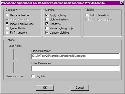
DEdit remembers your settings from session to session, but you must set them the first time you run and may need to change them if you’re working on more than one project. Our first important parameter is Project Directory , which informs Processor where the files for your game are located. You should set this to the full Windows path to the folder where your game’s .DEP file lives. This enables Processor to get any necessary information out of textures in the game. Since some textures have lights or other special effects, it’s important to make sure you have the right value here.
When a brush edge meets another polygon’s edge not at a vertex, this forms a situation known as a T Junction (the name comes largely from the fact that it does indeed look like a T when the edges are perpendicular to each other). This can result in pixel-sized gaps in the final image, most commonly known as sparkleys . You can use the Fix T Junctions function to insert a new vertex into brushes that have T Junctions on their edges so that the these gaps can be avoided. Ideally it is best if the level artists handle resolving T Junctions since using this feature can occasionally result in sliver-like polygons.
The second is the Log file check box. Checking the box tells Processor to store a journal of its activities on the hard drive. It will also display this information while it runs, but this is still sometimes useful. For instance, if a level causes Processor to crash, you can use the log to figure out what part of the compile the crash happened in.
Last is the Extra Parameters field. You can use this field to specify any command line option that Processor supports. It’s highly advisable that you look over the list.
Types of Compile and Their Advantages
The first type of compile is the quick compile. If your level is under heavy construction, hasn’t been sealed and you only want to look at a few changes you made to lighting or brushes, this is the type of compile to do. In this case, you only care that geometry is built and the level is lit so that you can look around. You must set Import Geometry and should probably set Ignore Hidden , Import Texture Flags and Apply Lighting. If your level makes heavy use of lights and the lighting stage takes a long time, set Vertex Lighting Only for a speed-up.
The second compile is a more thorough (although not full) compile. This is used when you want to check the quality of lighting and your geometry placement, as well as to get a rough idea of polygon counts. Set all of the flags listed above except for the two for lighting speed-up, and also the Light Animations button, which tells Processor to build the lightmaps for any animated lights you’ve added. Last, set the Full Optimization flag and the Fast Approximation flag. These tell Processor to generate visibility data, but to build it quickly instead of accurately (which would take longer).
Next is the full compile. Check all the options from the thorough compile above except for Fast Approximation . For a really thorough compile, you can vary the settings of the Less Polies/Balanced Tree slider (higher is more optimized) in the Advanced section. Generally, the slider should be near the top, but perhaps one notch down. Having the slider all the way up can cause the compile to take longer and sometimes causes errors.
This compile is much slower, but since the Processor works its hardest to make the level fully optimized, the level will run much more smoothly within the game after a full compile. This is the only compile you should ever run on a level that’s about to be released. All other compiles sacrifice in-game performance for reduced compile times. No user will care if the level took six hours for you to compile or six minutes as long as their frame rates are high.
The last compile type (entities only) is used when the only changes you’ve made in a level involved entities and not brushes. For example, if you tweak the values of your lights and then recompile, you haven’t changed any brushes. In these cases, the Import Geometry checkbox will not be grayed out, allowing you to uncheck it. When you run Processor, instead of building your geometry data from scratch and throwing out your visibility data, Processor will retain them and just write out the new entity settings. This leads to a much faster compile, especially on large levels. However, this type of compile can occasionally lead to problems in the output .DAT file and shouldn’t be used on a level that’s about to be released to the public. As always, use only a full compile on such levels.
Once you actually run Processor, the dialog will change to a log window and a display of progress bars showing compile progress. If you read the log window you can learn a lot about how the level is being handled. Some indicators you should watch for:
Number of Unseen Polies Removed: 0 — Watch for a message stating the number of removed polygons. If there’s a low number in relation to the total number of polies (especially zero), your level may have a leak. See the optimization section for more on leaks.
** Couldn’t find any textures. (Is project path set?) — This message usually indicates that you haven’t set your project path correctly. Usually not a problem, but if your game uses texture effects it can cause issues. Check the project path setting.
Found 1 problem brushes — This warning indicates that Processor found a brush it doesn’t think is valid. You can use the SelectProblemBrushes parameter to track these down, and should do so as soon as they appear.
Optimizing Your Level
It’s actually fairly easy to make a gorgeous Notre Dame-scale cathedral in DEdit. Once you know the basic controls, you can pretty quickly lay out the brushes, apply the textures and add in the lighting necessary to make such a structure. However, it is also extremely easy to build a level that:
- Will not compile
- Will take far too long to compile
- Will run poorly in the game even after a full optimization
This is truly where the science of level design begins to take a back seat to the art. Though there are some basic rules and a lot of guidelines to optimizing levels, the best way to learn good optimization techniques is to experiment and to carefully observe the results you get inside your levels. You must think about optimization right from the moment when you first begin designing your level, and you must watch the performance of your level every step of the way as you build. Unlike any other computer art product, computer games are rendered in real time , and this restricts you substantially in what you can get away with in your levels.
Factors That Cause Levels to Bog Down
Levels can become bogged down for a number of reasons. The first of these is high polygon counts in a scene. Even a simple empty room that has only walls, floor and ceiling can be made up of several hundred polygons. In order to apply lighting and tune the level’s performance, the brushes that you specify inside DEdit are broken down, juggled around and reshaped by the Processor as it builds the in-game .DAT file out of your .ed file. As mentioned above, this process is one of the reasons why you can’t edit a .DAT file in DEdit. To measure the polygon counts in your game, you use the ShowPolyCounts console command. As a general guideline, the game designers for AVP2 kept multiplayer levels to around 700 polygons/scene in general on multiplayer levels and 800 or so for single-player levels where frame rate was not as vital. It’s important to perform some tests of your own on your target platform to develop your own standards.
Lighting a level via lightmapping requires that large brushes be broken down into smaller chunks. This usually happens along texture boundaries. Thus, if you have a large room with a 64x64 floor texture, the floor may be broken up into dozens of 64x64 chunks when in the editor it is shown as a single brush. The reason this is done is to create the lightmap textures, which give the floor lighting. In the case of a moderately large room, this may add 200 polygons to the scene, but in some very large rooms it can add 400 or more polygons. It’s important to take that overhead into account.
There are ways to reduce this press somewhat. The first is to try to break up large spaces so that only some of the space is visible at a time. The second, useful in outdoor areas without great ground detail, is to scale up the texture on the floor. Often, a 64x64 dirt texture looks acceptable if scaled up to 128x128. In some cases it even helps give a sense of scale to the outdoor room. It’s important to test this technique yourself and decide whether or not you like the result.
There are also brush properties that you can use to affect the method used to light your brushes. The LMGridSize parameter listed in the WorldInfo string section describes how you can scale up your lightmaps in order to reduce the number of polygons created for lightmapping, which can lead to a decent savings in poly counts for large rooms. In many outdoor cases (one of the most common places where problematically large rooms appear), using Gouraud or flat shading can prevent subdivision while still giving a good light effect.
The second cause of high counts is complexity. It’s very hard to resist the urge to put every detail into your geometry instead of using textures to create detail. However, it is much more expensive to add detail using geometry than it is to imply detail through tricks of the eye, lighting and texturing. Avoid nonfunctional detail that can be added through textures like molding/trim, curlicues, grooves and bumpy surfaces. A level designer’s art is figuring out how to imply detail. Ask your texture artists to build a grooved surface or the face of a curlicued building ledge, and then apply that texture to a simple flat surface. Use as few sides as you can get away with on your columns and carefully consider how to build each shape with the fewest polygons.
Another typical cause of high counts is intersecting brushes. Every place where one brush touches another, the processor splits the touched brush in order to remove the hidden sections of each brush. However, this can drive counts up very significantly. A large, square room that’s normally lit would be subdivided into a simple grid of square brushes. If you place a square column in the middle of the room, the room’s still split along a square grid, since the splits around the base of the square column run parallel to the grid of splits made for lighting. However, if you put down a 12-sided column in the middle of the room, split lines run out from each of the 12 vertices that make up the base of the column. These lines disrupt the even pattern that existed before and scatter new brush splits throughout the room. You can observe this by using the DrawFlat and ShowSplits console commands.
The best way to avoid this problem is to carefully pre-plan before adding details in areas where their effects will be drastic. One way to do this is to bind such objects in a WorldModel in cases where that won’t affect the object’s functioning. Also, in many cases such as light fixtures and some columns, you can build your fixture and then move it 1 to 4 units away from the surface it would normally be touching. That prevents the split, and in many cases the player will never notice the difference. You must be careful using this technique, however. If you place a light in the right location, it will give away what you’ve done since the lifted object won’t cast a proper shadow.
Another issue that increases your polygon counts in a room is visibility leaks. To explain, the computer and the player see the level in different ways. The player can’t see anything that’s behind a solid wall or any solid surface. However, the computer always looks just a little bit ahead and pre-draws some objects that may not yet be visible to the player. This is for two reasons: One, the computer estimates cautiously when it decides what the player will be able to see. Two, the computer pre-loads some geometry that it thinks the player may soon be able to see in order to spread out the press of loading the polygons and textures.
This usually comes in the form of a wall or other fixture in the next room that adds to the poly counts in the current room. Sometimes the increase in counts makes very little sense. You can have a very small room without any real detail such as an entryway with the polygon counts of a much larger, more detailed room. If you look around in a room like this, you can almost always find either a hallway into another more detailed room or a leak to the outside of the level.
Troubleshooting Visibility Leaks
Two useful console commands come into play when troubleshooting visibility leaks: LockPVS and Wireframe . The first command, LockPVS , tells the engine to continue drawing whatever is currently visible to it (the Potentially Visible Set ) and not to load any further brushes into the world until it’s un-frozen. Use this when you’re getting high counts in a particular view and want to see what’s being drawn in another room. Once you get the high counts on your screen, enter LockPVS 1 on the console. After that, you can walk the area and see what the engine’s drawing. Only objects that are visible from the point where you locked the PVS will be drawn.
The Wireframe mode is harder to work with but more flexible. It switches your view to a wireframe view of the level. Since all brushes are transparent in wireframe view, you can see right through a wall into rooms on the other side. This means you can also see what brushes are being drawn in rooms other than the one you are in. Though it takes some getting used to, this mode makes it possible to figure out exactly when and where the view of a room or object is cut off, making it extremely useful when you want to check your visibility blocks. This command should be used in conjunction with the ForceClear command if you get bad redraw effects when WireFrame is turned on. Some games do this automatically. You may also want to use the DrawFlat command to turn off textures, which makes it easier to see the wireframe lines.
You can break visibility between rooms most certainly using a corridor with a pair of 90-degree turns in it. A U-turn should totally cut visibility, and an S-turn with the proper length of corridor in between the two turns will almost always work. Below that, controlling visibility becomes an art. Often, you will be amazed by what the engine decides you can see from a given point. It’s important to carefully walk your level and watch polygon counts for this reason.
Note: If you haven’t done a Full Optimization compile on your level, you cannot rely on the visibility or poly count results you obtain. Full Optimization cuts down counts far, far more than a Fast Approximation does. Similarly, if you don’t compile with optimization turned on at all, your whole level is visible from all points, leading to counts that are much higher than they will be after optimization.
In order to increase your chances of blocking off line of sight between areas, there are several things you can do. First, make use of kinks in between areas as described. Second, make sure that walls extend from the floor of a room to its ceiling. Third, make sure your walls fit snugly together. Fourth, keep the number of connecting doors, windows or vents between rooms as low as is reasonable so that you can more easily troubleshoot. Fifth, treat your outdoor areas in the same fashion, dipping your sky portal brushes down like a ceiling to close off one region of the outside from others. Use hills, hedges and tall buildings as walls to reach up and touch these sky brushes, thus completing the seal. The last tool to help you close off one area from another is the hullmaker brush.
Working With Hullmakers
Hullmakers are special brushes whose Hullmaker property is set to True. To make a hullmaker brush, you switch to Geometry Mode, and then lay the points for the brush you want to create. The resulting brush has a zero thickness (which is as you want it). You should place hullmakers in doorways or hallways where you feel visibility should be blocked off but you can still see polygons in the next room. Make sure that your hullmaker completely fills the doorway or hole that you are trying to block, and that the only property set to True on the hullmaker brush is Hullmaker . The player should never see these brushes inside a game level. Their sole purpose is to split the hulls of the level where they’re placed, encouraging the engine to block visibility there.
Hullmakers do not work 100 percent of the time; often, the engine decides that despite the split the player can still see past and into the room beyond. Sometimes, placing hullmakers can even split up brushes in ways that drive up polygon counts. Don’t dump hullmakers into a level expecting miracles. Pick a problem area and carefully add hullmakers or modify the layout around the area until you see the results you want
The last way to reduce polygon counts is to make sure that your level is sealed . The best way to think of your level is as a submarine or spaceship: right outside it there is a bad, unfriendly place. The interior of the level should always be isolated from the outside by a solid shell of brushes, none of which are bound to WorldModels, have their Invisible flag set, or have their Detail Level set to 1 or higher. In other words, it should be impossible to see or reach the outer space around your level. This is where careful brush creation habits and compiling regularly while you build are helpful. It’s much easier to catch a leak when you first cause it than after you’ve built an entire room.
Plugging Leaks
If your level does develop a leak, you can use a leak file generated by the Processor to help find it. To create a leak file, enter the command string –leakfile myfile.leak in the Extra Parameters field of the Processor. Once the Processor makes its leak file, load it into DEdit using the World menu to select Debug , and then click Load Leak File . This helpsyou to follow the path that appears until you find the hole.
Plugging leaks is important for three reasons. First, leaks can cause parts of the outer shell to be visible inside the level, unnecessarily increasing your counts. Second, leaks keep the level’s outer shell from being removed by Processor, increasing the size of the level’s .DAT file on disk. Last, if Processor has to do visibility calculations for the outer shell, it will take a great deal longer to complete. It pays to plug your leaks.
Another concern is a factor called overdraw , which is the number of polygons drawn on screen that are actually out of the player’s view behind other polygons. This is related closely to the visibility optimizations referred to previously. You can often find high levels of overdraw in rooms with lots of detail: columns, low walls, complex fixtures and cracks can all lead to overdrawing. Overdraw in a scene is measured using the ShowFillInfo console command. In the development of the game Shogo , for instance, values of 2-3 here were considered acceptable and values of 4-6 were danger signs. Once again, testing on your target platform to obtain figures for your own game would be wise.
Besides geometry-related factors that may slow down your game when it’s running, you can also get significant slowdowns if you use too many textures or several overlarge textures in a scene. Even in the age of AGP, if you use a 512x512 texture for everything from tiles on the bathroom floor to murals to the nameplate on a door, the game will run more slowly. As with many problems, this is best addressed in the design stages rather than in the testing stage.
You should try to resist the urge to use the largest texture possible and instead work to find a balance between a texture that looks good and is small in size. Objects that won’t get much scrutiny like floor/ceiling tiles, wall-to-wall carpets and grass should usually be given small textures. Objects that the player will focus on (view screens with data, pictures, signs) can use higher-resolution textures. The console command ShowTextureCounts provides information on textures for help in troubleshooting.
Entities can also affect game performance. If you build a huge particle fountain that creates 1000 particles every second with a decay time of 10 seconds on each particle, the engine is going to be very busy keeping track of the particles. Likewise, large, moving objects such as props made from WorldModels can slow the engine down as it tries to manage their physics.
Character models and AI can also affect frame rate. A level that runs fine with just the player on it can bog down seriously when two very intelligent AI enemies are added to it. Likewise, a Boss character with thousands of polies in her character model will slow the engine much more than a minor character with just a few hundred. Be careful how you code, design and place your AI. Also, be sure to test the results to make sure you haven’t stressed the system too much. The ShowTickCounts command gives useful information for figuring out these sorts of generalized issues by listing what portion of the engine’s time is spent in what area, be it rendering, sound or game code.
As mentioned before, optimization is more art than science, and it takes practice. The warning signs of trouble you should always heed are low frame rates, high polygon counts in a scene, and sudden jumps in the length of time it takes to process your level. Any of these should make you take notice. Immediately backtrack and figure out what has caused the issue. Even if you don’t do anything to correct it at the time, performance issues are almost always easier to fix if they’re identified early. It is heartbreaking to have to discard a level that is completed but completely unworkable, and you will do so if you don’t pay careful attention to optimization throughout the construction process.