I get asked this somewhat frequently, so I guess it is better for me to explain it once in a post rather than to everyone who asks. If anything is unclear, just ask me about it! Also, if you have not seen the latest demo, take a look now. Also, please vote on Steam Greenlight (cough cough self promotion).
Voxel Generation
- VQ is written with OpenGL, GLSL, C++, remote javascript via websocket (runs without it, just for the remote editor), and potentially Lua in the future.
- The majority of voxel generation and rendering occurs in GLSL, but higher level things are determined in C++ (i.e. where objects should be placed, the parameters specifying object materials and types, etc).
- How is is possible to render billions of voxels to screen (without an sort of compression like octrees), when that would clearly wipe out GPU and/or system memory? The trick is that voxels are rapidly generated, rendered, and discarded. Even though the voxels are discarded, collision detection is still possible as explained later.
- There is only one buffer that gets written to for voxel data, and this buffer is only bound by maximum GPU texture sizes. It writes to this buffer to generate the voxels, then renders those voxels to a bitmap so that they are stored in a chunk or page (I use the terms "chunk" and "page" interchangeably quite often).
- From there, the program can just place these pages on the screen in the appropriate position, just as it might with a tile-based 2D or 2.5D isometric engine.
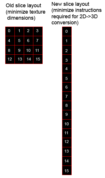
- You can't easily render to a 3D volume (there are ways, like this). Or you can just do ray tracing and not render each voxel implicitly. I don't touch 3D textures, and every single voxel is explicitly generated. So how do I avoid 3D textures? I just use a long 2D texture and treat it as a column of slices in a volume. This texture is currently 128x(128*128) in size, or 128x16384, but it the size can be changed, even in realtime. 16384 is the maximum texture width on most modern cards (and like I said, I'm building this over a 3 year timeline, so that might improve or become the common standard). Here is the old slice layout and the new layout:
Rendering Steps
- Run the voxel generation shader on the 2D slice texture.
- For each point on the 2D slice texture, determine the corresponding 3D point (clamped in 0-1 range). That is, based on the y coordinate, find the current slice number (this is the z value). Within that slice, find out the y distance from the top of the slice, this will be the y coordinate. Lastly, the x coordinate is the same as it would be on a normal 2D texture. Here is some glsl pseudo code (there are better / faster ways to do this, but this is more readable):
uniform vec3 worldMin; // the max coordinates for this chunk
uniform vec3 worldMax; // the min coordinates for this chunk
uniform float volumePitch; // number of voxels per chunk side
varying vec2 TexCoord0; // the texture coordinates on the slice texture
// may need this if GL_EXT_gpu_shader4 not specified
int intMod(int lhs, int rhs) {
return lhs - ( (lhs/rhs)*rhs );
}
void main() {
// 2d coords input
vec2 xyCoordsIn = vec2(TexCoord0);
// we are trying to find these 3d coords based on the
// above 2d coords
vec3 xyzCoordsOut = vec3(0.0);
int iVolumePitch = int(volumePitch);
int yPos = int( volumePitch*volumePitch*xyCoordsIn.y );
// convert the xyCoordsIn to the xyzCoordsOut
xyzCoordsOut.x = xyCoordsIn.x;
xyzCoordsOut.y = float(intMod(yPos,iVolumePitch))/volumePitch;
xyzCoordsOut.z = float(yPos/iVolumePitch)/volumePitch;
vec3 worldPosInVoxels = vec3(
mix(worldMin.x, worldMax.x, xyzCoordsOut.x),
mix(worldMin.y, worldMax.y, xyzCoordsOut.y),
mix(worldMin.z, worldMax.z, xyzCoordsOut.z)
);
}
- Once you have this 3d point, you have the world coordinates based on the position in the slice texture that you are rendering to. You can also get object-space coordinates based off of this coordinate and the object position in worldspace. Using these coordinates we can do all kinds of generation.
- After generating voxels for the current chunk, it renders the voxel data to screen, then the buffer we used for voxel generation gets discarded and reused for the next chunk. To render, it just shoots a ray from the front of the chunk to the back - I won't go into detail explaining this because others have done it much better than I could. See one example of how this is done here. In my case, the volume cube that gets ray marched is isometric, so it is exactly the shape of an imperfect hexagon (with sides that have a 0.5 slope, for clean lines, in the style of traditional pixel art).
- What gets rendered? Depth, normals, and texture information. This information is later used in the deferred rendering to produce a result.
- Each chunk gets rendered to a 2D texture. These are then just rendered to the screen in back to front order (you can do front to back, but it requires a depth texture). As these chunks fall out of distance, their textures get reused for closer chunks.
- Even though voxel data is discarded, collision and other calculations can be performed based on the depth values that get rendered, within the shader, or on the CPU side using the info of the closest objects.
Grass
- Grass is rendered in screen space. There still are artifacts from this method, but there are ways around it.
- Each blade is either a quad or single polygon (optional).
- It renders every blade to the same space on the screen (at a user-defined interval of x voxels), but the length of the blade is just based on the texture information under it.
- If there is a grass texture under it, then the grass blades have a normal length in that spot. Otherwise, they have a length of zero.
- This information is actually blurred in a prepass so that grass fades away as it approaches non-grass areas.
- The grass is animated by adding up some sine waves, similar to how water waves might be produced. For most performance, grass can be disabled. Alternately the grass can be static for some performance increase. Animated grass takes the most performance but does not drain resources too much surprisingly.
- Grass can be applied to anything, with different materials as well. Could be useful for fur, maybe?
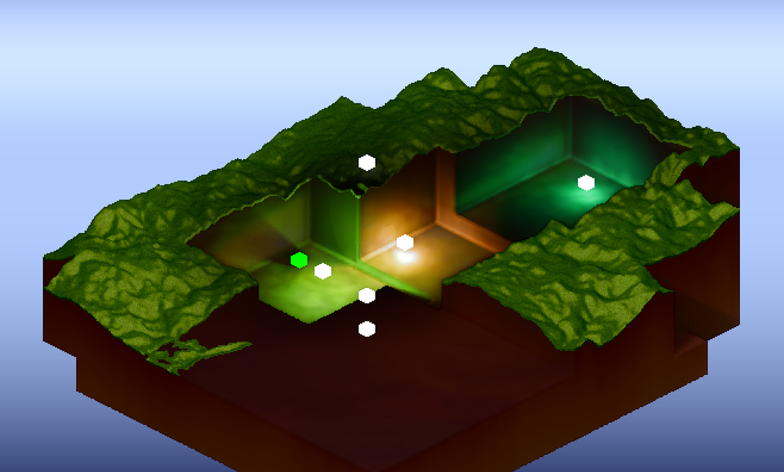
Water and Transparency
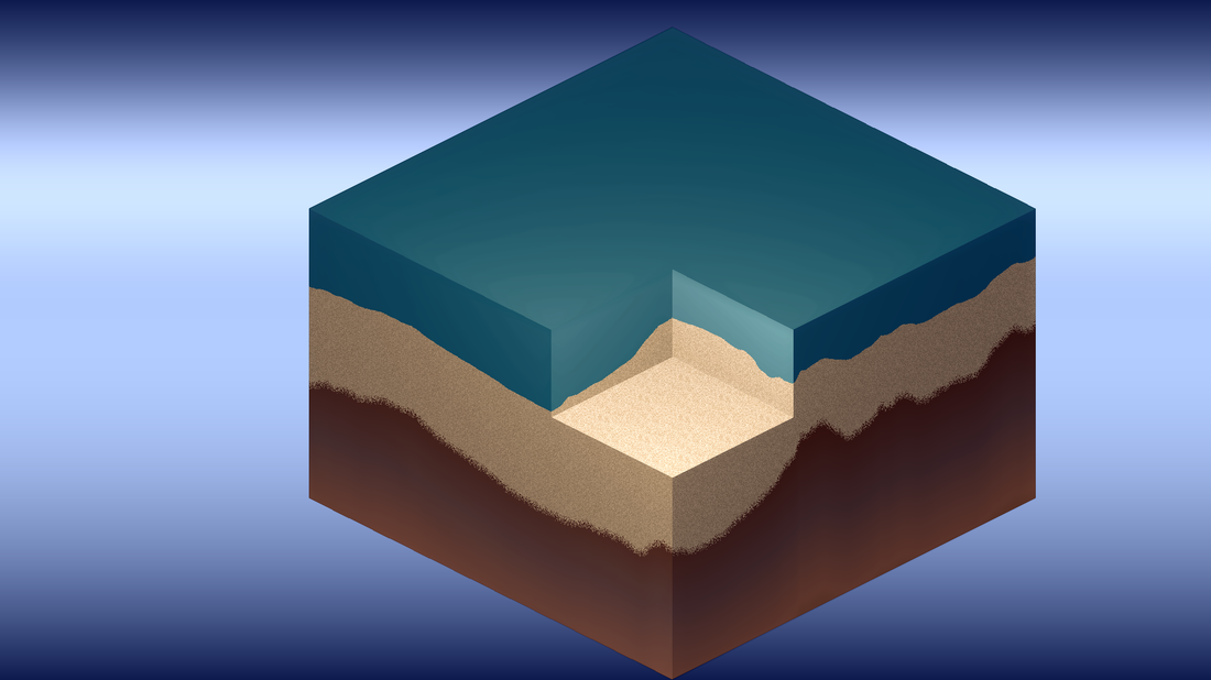
- Water need not be at sea level, and it can fill any space (not necessarily cubic) (you can see in some of the demo video that the water does not flow through building walls).
- Water could potentially flood an area on breaking its source container, but this is not yet implemented.
- Water is rendered to a static area on the screen, as in the screenshot above.
- This area then has a ray marched through it to produce volumetric waves (this is done in screenspace).
- Water and transparent voxels are rendered to a separate layer.
- The deferred rendering is done in two passes, one for each layer.
- The layer under transparent objects is blurred for murky water, frosted glass, etc (simulate scattering).
- These results are then combined in a final pass.
- Transparent objects are subject to normal lighting. In addition, they reproject light (as seen with the windows at nighttime and the lanterns). This is not really phsyically correct, but it looks much more interesting visually.
- Water has multiple effects. If you look very closely, there are bubbles that rise. There are also (faked) caustics. There are even very subtle light rays that move through the water (also faked). Lots of faking. :)
Lighting
- Lighting, as mentioned, is done in a deferred pass.
- All lights are currently point lights, but spot lights could easily be done (just give each light a direction vector and do a dot product between the current light ray and that direction vector). Additionally, directional lights would be trivial as well.
- The light count is dynamically adjusted based on how many lights fall within the screen area (in other words, lights are culled).
- Lighting utilizes Screen Space Ambient Occlusion (SSAO), ray-marched shadows, multiple colored lights, radiosity (lighting based on light bounces), and fairly involved (but very unscientific) color grading. The number of samples for shadows, SSAO, etc can be adjusted to tweak between better performance and better visuals.
- Lights have more properties than just color and distance. Any light can sort of do a transform on the material color (multiplication and adding), which allows you to easily colorize materials. For example, in reality if you shined a red light on a blue object, the object would be black because a blue object reflects no red light (I think?). In this engine, you can colorize the object.
- You can even "flood" areas where the light does not hit to ensure colorization (this is done with the global light at nighttime to ensure everything gets that blue "moonlight" tint, even if under a shadow).
- Colorization is not really a simple function - it is hard to get a balance of luminosity (which tends towards white, or uncolored light) and color, which tends away from white or grey. You can see in the screenshot above that lights get brighter as intensity increases, but they still colorize the areas (box color does not represent light color here - all boxes are white regardless).
- On top of everything else, I do a saturation pass which basicallly averages the light color at that spot, then "pushes" the light color away from that average using a mix (i.e. mix(averageLight, coloredLight, 1.2) ).
- In general, I find it best to avoid simple lighting as it will produce flat, ugly results. Fake it as much as you want - this is as much of an art as it is a science. :)
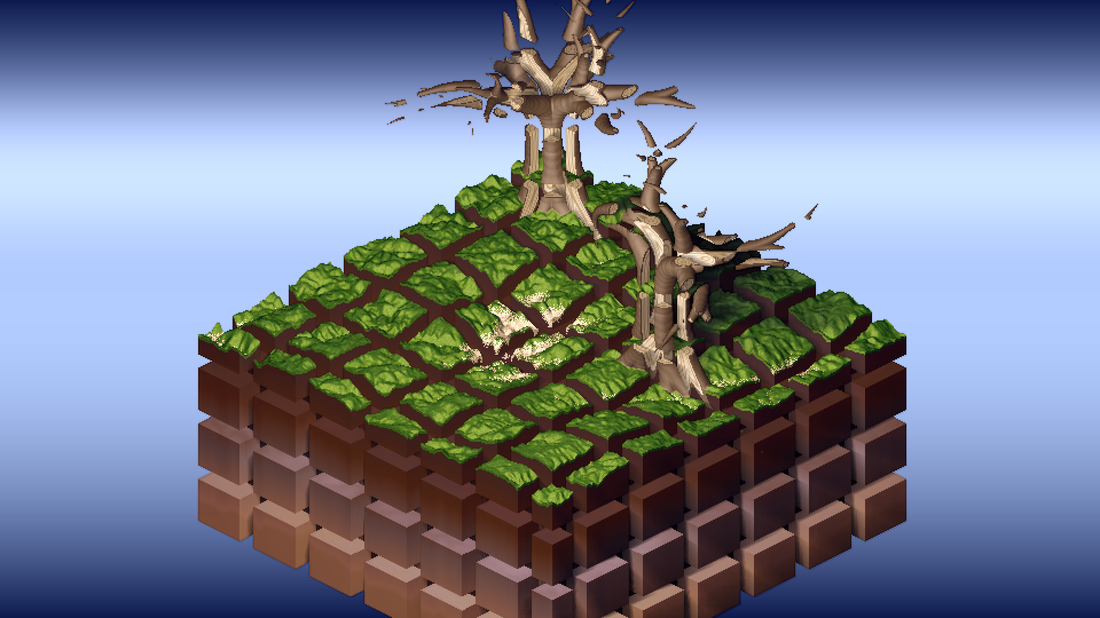
Trees
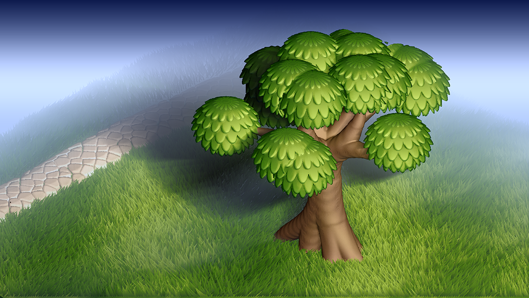
- Trees are all unique. Only two types are shown (barren trees and this Dr Suess crap that I accidentally produced). Many more types can be produced by changing the rules (number of generations, number of splits, split uniformity, length, split angle, etc).
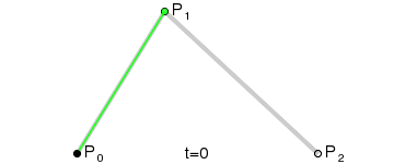
- The trees use quadratic Bezier curves for the branches. Each Bezier curve has a start radius and an end radius. It determines within the voxel generation how far it is from all the nearby Bezier curves and produces a result based on this, which determines the wood rings, bark area, etc. This distance calculation is relatively cheap and not 100 percent accurate, but good enough for my purposes.
- The distance calculation just uses line-point distance. The basis for this line is determined from the tangent (green line in the image above) and it also takes into account the other base lines to determine the closest t value for the curve (clamped in the zero to one range of course).
- In order to simplify the data structures and rules for the trees, there are separate rulesets for the roots and for the rest of the tree - this seems to cover all cases I can think of for plants so it probably will stay this way.
- The leafs are just spheres for right now. Each sphere uses the same procedural texture as the roof shingles, just with different parameters. This produces the leaf pattern. A cone shape will probably be used with the same shingle pattern for pine trees (again, I prefer style and simplicity over total realism).
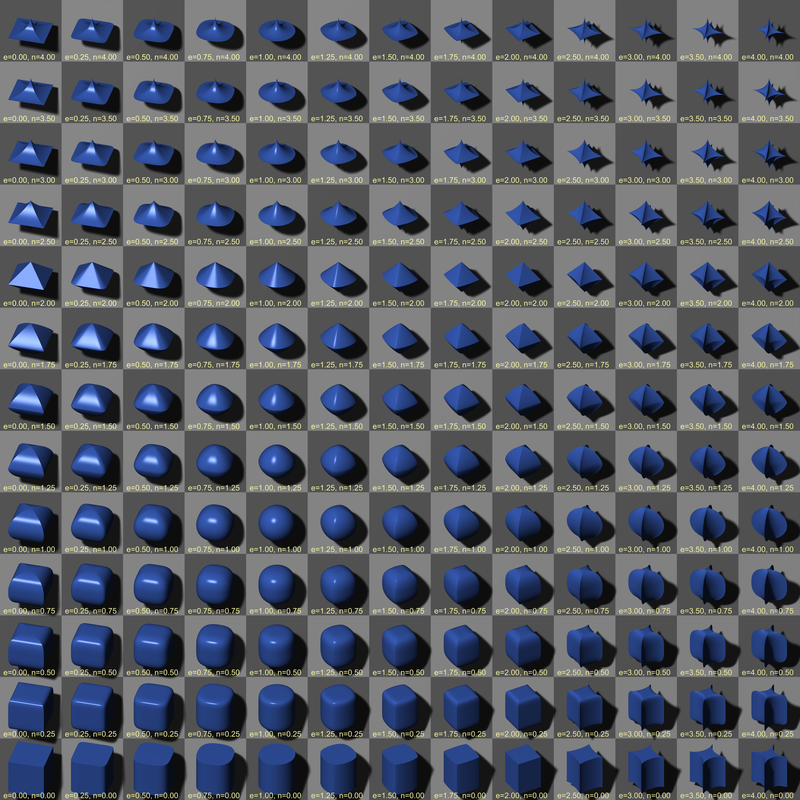
Geometry and Primitives
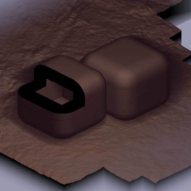
- Geometry uses superellipsoids and a "slice-27 grid" (best term I could think of). What is a "slice-27 grid?" If you are familiar with Flash's slice-9 grids, it is the 3D equivalent. Basically, think of it like a rounded rectangle, only 3D, and the corners can be almost any shape.
- You can specify many things on a primitive, including corner distance (independently even for xyz, like if you wanted to make a really tall roof), wall thickness, or a bounding box to determine the visible region (useful if you want to, say, cut off the bottom of a shape which would otherwise be symmetrical).
- Building segments are a single on of these primitives, only they use very advanced texturing to determine the floors, beams, building level offsets, and so forth. Variations in the building, such as doors and windows, are separate primitives.
- You can easily combine primitives using Voronoi style distance (typically clamped to the xy or ground plane). You can also do more advanced boolean intersections and give various materials priority (for example, the roof is designed to not intersect into the brick, but its support beams are).
- Texturing occurs volumetrically in object space. Texture coordinates are automatically generated so as to minimize distortion.
- Texture coordinates are always measured in meters, so that it can scale independently of voxel size.
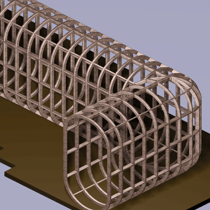
- Even special materials can be applied to joint weldings, such as the wooden beams that occur at this intersection above.
- UVW coordinates are generated that run along the length of the object, along its height, and finally into its depth (into the walls).
- Any material can be given a special id to distinguish it for when normals are generated later. You can see this effect in the boards above - their normals do not merge together, but instead they appear as distinct boards (by the way this is an old shot obviously and this distinction has improved much further).
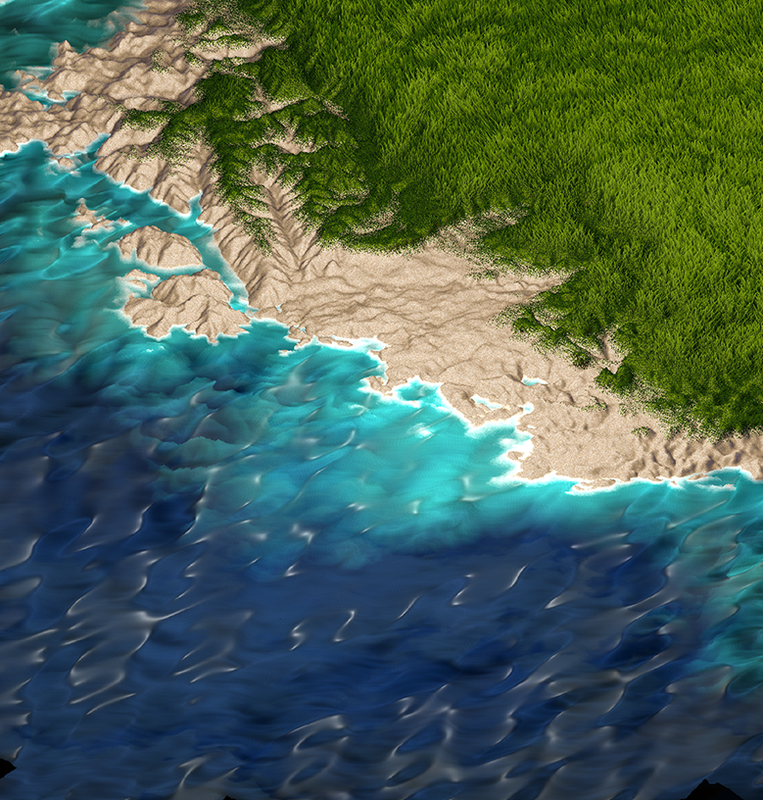
Map and World Generation
- The first thing that occurs in map generation is creating the terrain. It takes a bunch of heightmaps based on real world data. Getting this data is not exactly easy, but here is one way to do it.
- I take 3 heightmaps and combine them into an RGB image (could be 4 in RGBA). This is an optimization that allows me to do one texture read and retrieve 3 heightmaps at the same time. This is currently just done with 6 heightmaps overall, but each one is very big.
- I make this heightmap combo seamless in photoshop (look up tutorials on seamless textures in Google for how to do this).
- It samples from random areas on these heightmaps and stitches them together based on some simplex noise - you can almost think of it like using the clone stamp tool in Photoshop if you are familiar with that.
- This generates the macroscopic terrain. It recursively samples from this map (which is still seamless, by the way) in order to produce finer and finer details in the terrain, right down to the voxel level. Phsyically correct? No. Looks ok? Yes. :)
- So, I could set the sea level at an arbitrary value (say, half the maximum terrain height) but this lends itself to a problem: What if I only want x percent of the planet to be covered by water? I solve this problem by sort of making a histogram of terrain heights (i.e. how many pixels contain a given height?). It then lines up these amounts. If I want the planet to be 50 percent water, I simply look halfway down the line and see what the terrain height is there.
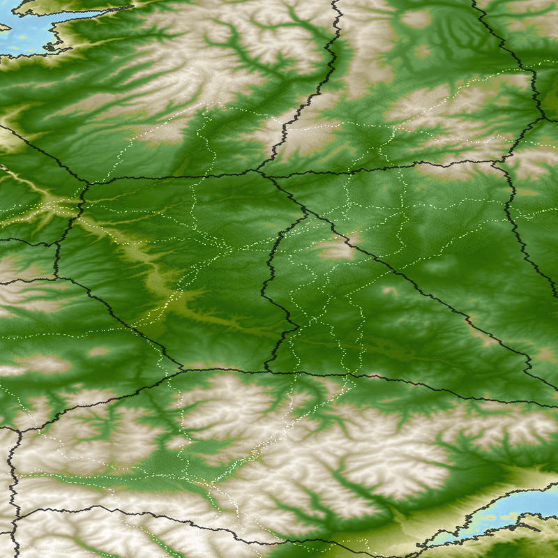
- Next, it places cities randomly that meet certain conditions (i.e. above sea level, even though cities can grow into the water with docks).
- City roads are built using maze generation, in particular recursive back tracking. Here is a great source of maze generation algorithms.
- This generation creates many windy roads, which is great for cul-de-sacs but bad for ease of transportation. I place main city streets at a given interval. Doesn't look great, but it works.
- Inter city roads were probably the hardest part. Seems like it would be an easy problem but its not. Finding a road from one city to another is relatively "easy" (it is actually quite hard on its own though), but what if two cities have roads that run close by each other? How do you optimize paths such that redundant roads are eliminated?
- Roads are generated by creating a line between two cities, and then recursively breaking that line in half and adjusting the midpoint such that the terrain delta (change in height) is minimized. There is a severe penalty for crossing water, so bridges are minimized. This produces fairly realistic roads that strike a balance between following terrain isolines and not having a path that is too indirect. After the line is broken down many times, it creates a trail of breadcrumbs as shown in the image above. Note how many redundant breadcrumb trails there are.
- It then dilates these points until they connect, forming solid borders. After that, it color-codes each region (like map coloring, kind of). See image below.
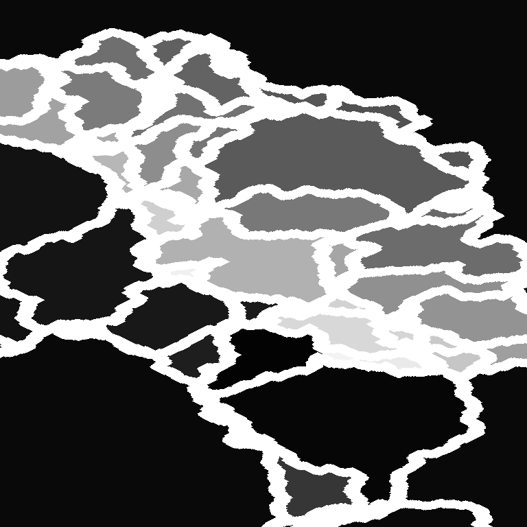
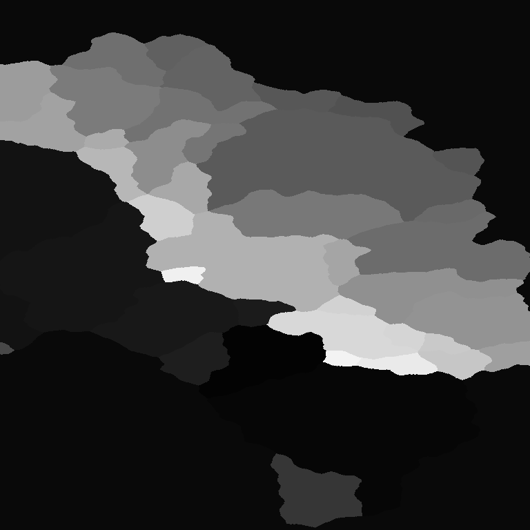
- Then the dilated regions are shrunk back down and the colored regions which are too small are merged with neighboring regions. Finally, roads are regenerated along these new borders.
- Ship routes are generated the same way as roads, only there is a severe penalty when measuring the delta if land is crossed. Ship routes do account for water depth as it is generally a good heuristic for avoiding land to follow the deepest sea route.
Conclusion
This really only covers a fraction of what goes into the engine, but I hope it answers many of your questions. If you have additional questions, feel free to ask. Thanks for reading! :)

Sounds crazy complex, but looks and sounds really awesome. You should post a gif or video of the animated grass! lol. Game looks like it will be really good, keep up the good work
Awesome stuff, the only thing that really bothers me is that it all looks like shiny plastic.
You may want to adjust the specularity a bit.