Steam, Tracks, Trouble & Riddles
Advanced Rigging Tutorial for Custom Rigs
How to setup a Rig in XSI Modtool, which do not have two legs?
by Peter (peegee) Graf
June 2011
Content
Introduction
Part 1: Preparation of the Model
Part 2: Inverse Kinematic Elements in XSI (Roots, Bones and Effektors)
Part 3: Let's Draw a Rig
Part 4: Constraints
Part 5: Controllers
Part 6: Knitting all together
Part 7: Plotting the Animation
Part 8: Exporting the Model and Animation
Part 9: Troubleshooting
Part 10: Conclusion DOs and DON'Ts
Appendix, Source Register, Links, Code
Introduction
Why another tutorial about rigging when there are millions around?
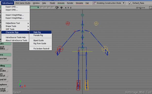
The reason for this: I did not found anything about really custom made rigs for the Source™-Engine.
Most of them are based on the ready made Valve-Biped-Rig. The character Easy Rider in my mod
Steam, Tracks, Trouble & Riddles can't use this type of rig, because it simply has no legs but a wheel.
Hence i had to investigate a custom rig.
This tutorial is for advanced users of XSI or Autodesk™ Softimage™ Mod Tool (XSI Mod Tool).
It covers the creation of a non-biped rig for converting into the Source™-Engine of
Valve Software Inc.™
The purpose of this tutorial is to learn and understand the creation of a rig forunusual structures
i.e. worms with 100 legs, buddha with 8 arms, robots with a wheel instead of legs, mechanics like the
Walschaerts-mechanism of a steam locomotive. It will guide you to a deeper understanding of the
rigging mechanism inside of the Softimage Mod Tool and how it will be represented in the source engine
after exporting.
Assumptions for this advanced tutorial:
.Autodesk Softimage Mod Tool 7.5* or XSI 7.01 (32bit)* or higher installed on your computer
- Good knowledge of XSI
- Knowledge of Modelling in Autodesk Softimage Mod Tool 7.5 or XSI
- Basic knowledge of rigs and inverse kinematic
- Basic knowledge of export and import with the ValveSource export addon
(* I will call it XSI from now on, it will save some paper)
You may skip this tutorial if your character has two legs,
For this kind of bipeds the Valve Biped Guide provides the best solution for the creation of your rig.
A tutorial about the valve biped you will find here:
Developer.valvesoftware.com
This tutorial DO NOT cover:
- Modelling or texturing in XSI
- Compiling your character for the Source™-engine
- Setting up a character inside the Hammer™-Tool
- Detailed description of enveloping or skinning of your model onto the rig
- How to make a good espresso or cake
Part 1: Preparation of the Model
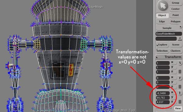
Most important, however your model or character will look like, is to position it right in the middle of all
dimensions x,y and z and above the xz plane. Most objects live above the floor, so they should not have polygons below 0 of the y axis.
In XSI you see the transformation parameters at the right side of the interface. They should have
1 1 1 for scaling, 0 0 0 for rotation and 0 0 0 for translation. You achieve this by using
"Freeze All Transforms":
Your model will stay in the same state as before, but all values be set right for export.
The pose of the model or character should be a default pose. It can be the pose like a "T"
for characters with two arms. But if your character do not have arms or has an unhuman structure,
set it in a kind of idling or default pose.
Before you start rigging:
Check the size of your model. 1 unit in XSI equals 1 unit in Hammer. As far as i know 1 unit
represents 1 inch (2.54 cm). Gordon Freeman's height is 74 units, his box width and depth is 32 x 32 units. So grab a box and place it in comparison to your model. You don't want a mouse instead of an elephant.

Check normals and polygon integrity and have the right texture on it. Texturing, the RenderMap process
(baking of texturemaps) and all steps of modelling should be completed before you start the rigging.
It can save a lot of time! If you are NOT happy with your model in any way, don't start rigging, finish modelling first.
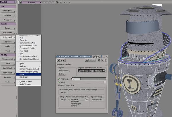
In this figure you see the property page of the Polygon Merge Tool. Merge the seperated objects into one
by selecting them and clicking "Poly.Mesh -> Merge" in the Model Toolbar. Set Tolerance to 0 and press the Merge-buttons on the bottom of the property page. You may hit Hide/Unhide on the top to hide the seperated objects, so only the merged result will be visible. If you press Delete, the source objects will be deleted.
It is NOT recommended to do so. Do NOT press that button.
You know what happened to Wheatley and GlaDos in Portal 2!
Part 2: Inverse Kinematic Elements in XSI (Roots, Bones and Effectors)
In this chapter is about some basics about the inverse kinematic elements you may find in XSI and how they are
represented later in the Source™-Engine world.
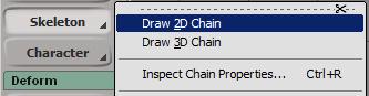
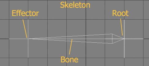
With Draw 2D Chain you can create a basic skeleton like this with three parts: the root, the bone and
the effector. This it how it looks in one of the views:
Here you can see how it is represented in the explorer (press 8) and the
schematic view (press 9)
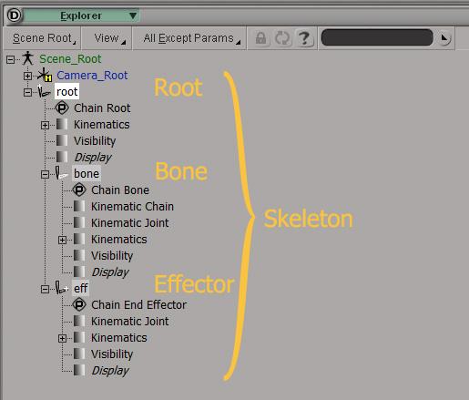
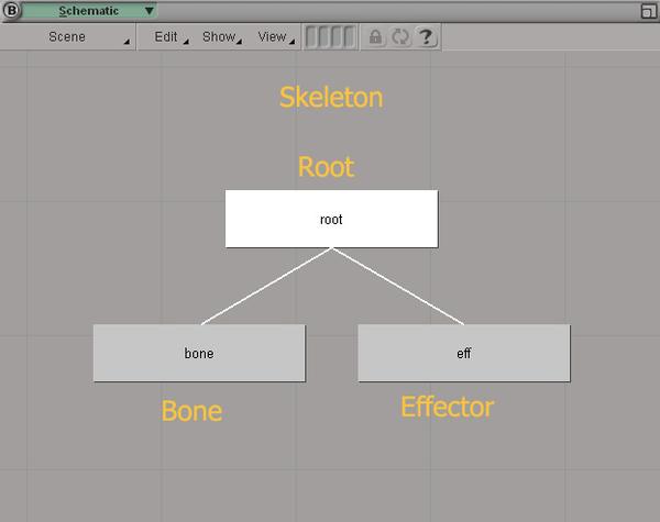
In the schematic view we can see, that the root is the parent of the bone and the effector.
The root will work like a hinge for the bone and define it's position, the bone can rotate around the root.
The effector will follow the end of the bone. It is possible to position it by translating or dragging and
to set the direction of the bone.
All is very nicely setted in XSI, if you like to do a conventional animation rendered with mental-ray.
BUT if you like to export it later to the source-engine: The only thing what is left over after export is the bone. Not a root, not a Model, not an effector.
There only one element, which can be exported like a bone: the Null. You can get from the
Primitives -> Null
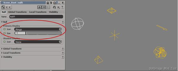
On the picture above there are some nulls represented by different icons as cross, rings, diamond and arrows. You can set this after selecting the null and press Alt-Enter. In the property page you may choose, which icon will be shown.
Nulls are nothing more than simple "points with an orientation and scale value". There is little difference to the bone of the skeleton. The bone is contrained to a root, that's it. After exporting them into a .smd-file, which we will need for compiling later, their names will be visible in the header of the .smd.
Here you see it again in the schematic view and the user camera perspective on the model.
These the two elements which can be turned to a rig.
Further proceding includes 4 Steps:
- Building up the skeletons according to the characters structure. That is in part 3.
- Create a "controller-rig" with the representing hierarchy of the character morphology, part 5.
- Create constraint-nulls on the "controller rig", as well see part 5.
- Knitting the controler rig and the skeleton together by using constraints, part 6.
Part 3: Let's Draw a Rig
Now let's go to the core of this tutorial and build up your customized rig.
Most important for this step is accuracy and concentration. Swich off your cel-phone, lock the door, evacuate
disturbing family members and switch off TV, Radio, CD-Player, iPod and all what can block your mind.
Take your time, don't be rushy.
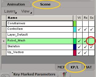
To have better workflow just place you model into a scene layer or group and set it to non-selection mode. This will prevent you from selecting the model by mistake. Just uncheck the layer under Se. The model should turn grey in all viewports.
Now go to the right view and draw skeletons according to your characters morphology.
You can adjust the skeletons with Skeleton->Move Joint/Branch or Ctrl-J.
You may move the skeleton root with transforms, but
and
You never, never may scale the bone!
This is very important, because if you have scaling values different to 1/1/1, after exporting they will snap back to 1/1/1 and your skeleton is spoiled and won't work in the source-engine.
Thats why it is so important, that the size of your model is A-OK! Again:
Another function do not work properly in XSI for skeletons: Duplication by symmetry. It is not recommended to use the Edit->Duplicate->Duplicate by Symmetry function. Better go the hard way, duplicate the skeleton and type in minus in front of the position values of the root and the rotation values of the bone.
Are you scared now? Good! That's the basic intention of this tutorial, to scare people and prevent them from doing nonsense. It's called carot-and-stick-motivation-method. Let's go on with a carot for you.

When you are finished and have created and placed all skeletons you may have another carot and take a rest.
You may now get a null from primitives. Do not move it, rotate it or scale it.
Name it MyRigParent. Place all skeletons as children to MyRigParent with the Parent function
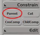
Right Mouse Button (RMB): Pick a child
Middle Mouse Button (MMB): Pick the Parent
Moving the skeleton roots to the parent object in the explorer (8) will do the same job.
Left Mouse Button (LMB): Terminate this action
Now it should look like this in the schematic view:
Have a carot! Take a rest! And don't forget to save the scene from time to time!
Part 4: Constraints
Constraints are very helpful relationships between objects in Softimage. You will have here a brief description of two kinds of constraints we will use especially for building controllers in part 5.
The benefit of constraints are that they can be set indepedent from hierarchies or parent-child relationship. The reason for you to learn the principle of constraints properly is that you might not have too deep levels of hierarchy, you should have only one level of hierarchy in your rig. "But what about the shoulder rotating the upper arm rotating the forearm controlling the wrist holding the fingers? That sums up four levels?"
I am sorry to say: Give up! Let's stop the tutorial here and got ot the beach. Four levels are not possible....?
Yes, we can! We can do it of course! We can do both with the help of another kind of rig, which will represent the hierarcy and the levels of our character skeleton structure.
For that we only need two kinds of constraints, the Position-Constraint and the Orientation-Constraint.
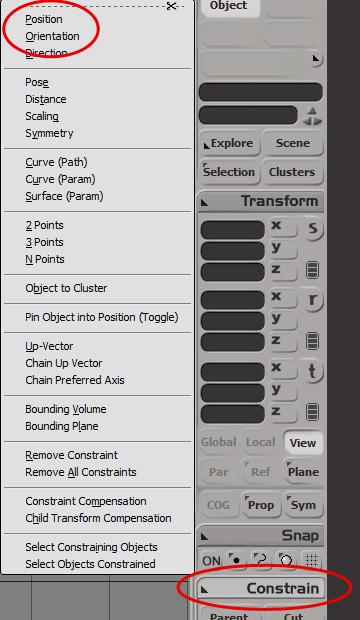
You simply select one object named "One", choose Constrain->Position and klick on another object named "Two". "One" will immidiately jump to the postion of "Two". A property page will show up, but for now we can leave this and close it. From now on you can't move "One"
translation: it is not deleted, but it won't show up any more.
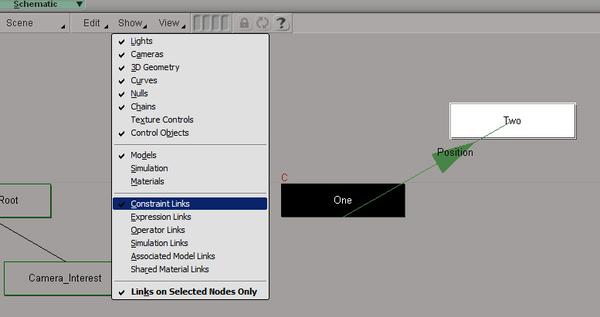
If your operation was successfull, you can see a line with an arrow in the schematic view between the two objects. "Two" will lead now "One". Constraint Links has to be checked in the Show menu.Better check on Links on Selected Nodes Only , otherwise it can turn to a jungle of lines, when we will have more contraints set.
The same will happen if you choose Constrain->Orientation. Instead of following the position "One" will have the same rotation values like "Two".
You can release this constraint with Constrain->Remove Constraint followed by clicking on the object which is the "leader". Or just use Remove All Constraints.
Part 5: Controllers
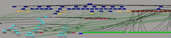
Oh dear, how we can control this bunch of relationsships? We need a special control level!
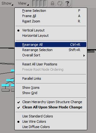
If your schematic view looks chaotic like the one on the picture above do following steps:
Use View->Rearrange All od Ctrl-R and Reset All User Positions.
I already mentioned the Show->Links on Selected Nodes Only check button.
It's a lot of work to create, position and contrain all the elements of a controller rig.
That's why I wrote a script for you in jscript just to train my brain a little bit.
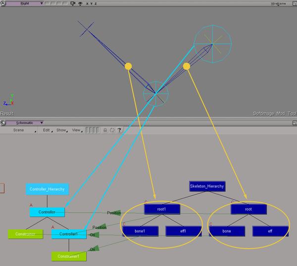
In the figure shows a simple example with two roots , 2 controller-spheres and 2 constrainer-nulls.
After executing the jscript, you only have to create the hierarchy with the controller rig braches to
represents the hierarchy of the characters morphology. BUT DO NOT MOVE OR ROTATE ANYTHING. In a classic biped rig the hip is on the top of the hierarchy, so that is the node with the highest position in the hierarchy. But it may vary and depends on your characters design.
You will find the script text at the end of this tutorial in the appendix.
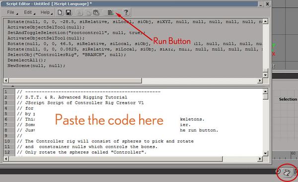
Paste the code into the script section of XSI. Set the script language to JScript under File-> Preferences.
Run the script pushing the script button.
Check the Schematic View an hava look at your new controller rig.
Advanced User may store the file as a button and create a button in your personal toolbar.
When this is done naming is a good idea. Do the naming as if your little sister has to understand it (the one in the cradle). Tipp: Have a look at the valve biped bone names.
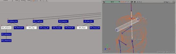
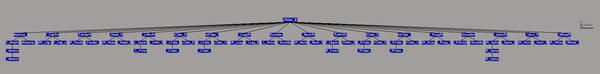
Here have a look at the hierarchy of Easy Rider, the robot in my mod Steam, Tracks, Trouble & Riddles after creating the controller rig.
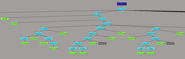
The cyan colored nodes are the spheres, the green nodes are the nulls. I called the spheres "name_controller" and the nulls "name_constrains". The little red "A" at the cyan nodes indicates, that they have an animation keyframe. You should not have a keyframe yet.
In the figure above you see the body controller at the top, followed by the spine controllers, followed by the shoulder, arms, hands down the tree. The blue node "EasyRider_ALL" is a model, which remains in the center, never rotates, never will be scaled.
When the hierarchy of controller-spheres has been created, it's time to do some "house keeping procedures". I placed every sphere in a layer (colored cyan), every constrainer-null in a seperated layer (green) and the skeleton I moved into another layer (blue). Every layer got it own color, so you may see clearly the differences.
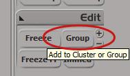
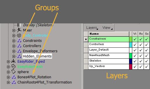
Additiontely I placed nulls (constrainers), spheres (controllers), roots, bones and effectors in different groups. These groups we will need later for handy selection and for hiding elements which should not be visible or changed.
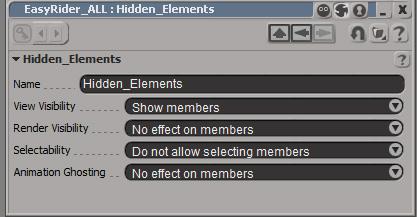
This property page will pop up, if you type Enter after selecting a single group in the explorer.
You may switch visibility and selectibility for all members of that group.
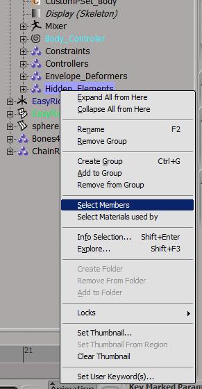
In case you like to select the elements in a group to perform a function on all of them simply select the group in the explorer and open the menu shown above with the RMB. Choose Select Members and all elements will be selected, not the group itself. Voilá. Housekeeping is done. Have a carot again.
And don't forget to save the scene from time to time!
Part 6: Knitting all together
Part 6.1: Controller-Rig
To prevent moving or rotating those elements by mistake I recommend to give every controller-sphere a keyframe. The offered Normal Pose function is not a good choice, it can lead to some problems. I never use Normal Pose options.
You should check now, if your rig is working fine. Rotate every sphere – the bones should follow in the right way. All elements should snap back to the keyframed pose, when you move the slider on the timeline in the lower part of the GUI.
If you are NOT happy with the functionality of your rig, fix the problems FIRST before you
continue. You can save a lot of time. Only in the unprobable case in which you are happy and everything is working fine, you have done pretty good work, the most of the rig construction is done. Waiter! One Carot please!
Part 6.2: Enveloping
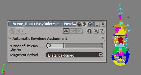
It's time to connect the character-mesh to the skeleton, the enveloping.
With the mesh selected you can choose Envelope-> Set Envelope in the Animate Toolbar.
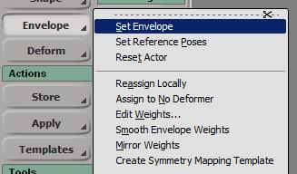
After that you click on the group "EnvelopeBones" in the explorer (You created this group a chapter ago
with the script execution).
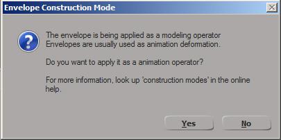
This message will appear, simply click "Yes".
(Congratulation! You are now owner of 20 dishwashers offered at eBay :-)
This window will appear after the eBay-bargain. Click it away. No dishwashers will be delivered then.
The most important on that action: the coloured vertices on the characters mesh indicate, that they will
be influenced by the bones of your rig. The next step is setting the right weights of influence to the vertices, but this i won't describe here.
A tutorial about enveloping you will find under
Developer.valvesoftware.com
Part 6.3 UpVector Constraints
It might happen, that some of you bones will "flip", when you rotate or change the controllers.
This is not nice, but it happens all the time due to the calculation inside the inverse kinematic
system. The solution to this are UpVectors. This can be little nulls to which the flipping bone
will be constrained with the Constrain->Chain UpVector
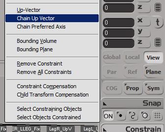
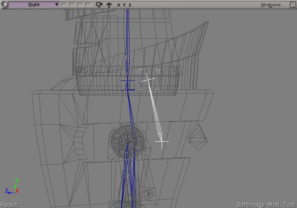
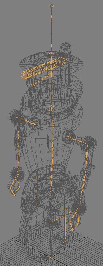
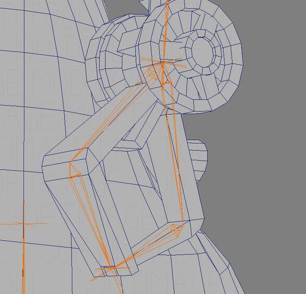
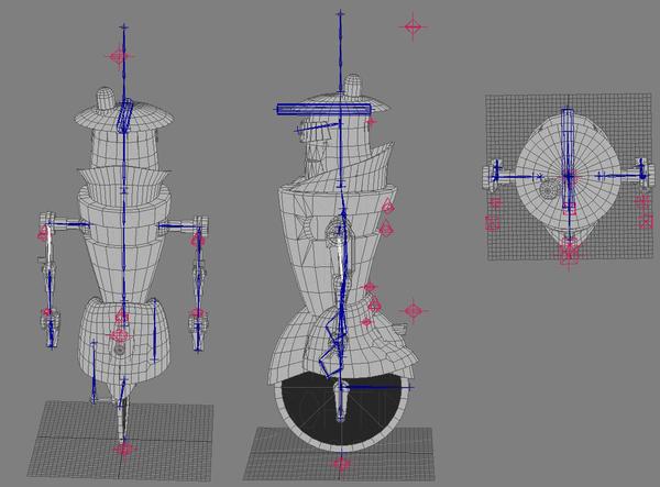
In the figure below you see, that the UpVectors (The red nulls shown as "diamond icons") are placed behind the bones. The arm and the spine bones are fixed by them. A better description of the UpVectors you will find in the user's guide of the Mod Tool (F1) under Constraining the Chain’s Up Vector (Direction).
Check your rig and your character again by rotating or moving all the parts.
Add the UpVectors as children to the top null of the the controller-hierarchy.
In case that you will find some errors: Don't worry or give up. It took me more than a week to build up a proper rig for my character. Take your time. Eat carot's, they are healthy.
Part 6.4 Rotation Limiter
There is another important reason why I had to construct the rig by myself: Restrictions of movements. The robot's arms can't move like a human ellbow, the human writs is more flexible than the mechanic claw, which acts like a simple hinge. For implementing something like a "Limiter" there is a simple solution in Softimage: Rotation Limits
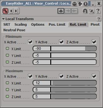
Select the controller-sphere which rotation should be limited and press Ctrl-K. A property page will pop up. Under the register "Rot. Limit" you can choose which rotation values will be limited. In the figure above all dimensions are limited in rotation. X from -90 to 12, Y from -5 to 5 and Z from -5 to 5 as well. Test your rotations after setting the limitations. The values are often not "intuitive". Z can turn to X or Y to Z, because the rotation values are local and the system changes because of the parent object is the reference.
Part 6.5 Surprise!
You made it! In case you have now a mesh enveloped to a rig, which can be controlled by the little spheres. Now save the scene please.
The spheres should still have this one single keyframe, you can move all keyframes together in one step to frame -1 in the Dope Sheet. Animation is not part of this tutorial. They are thousands of animation-tutorials in the net. My recommendation: Richard Williams "The Animator's Survival Kit"
Now let's animate your poses and gestures. I stored every gesture and animation in a separated scene.
Oh yes, I like to have things in the right place. Did you know, you can place your scenes in a named folder? Just press 5 and the internal browser of Softimage will be at your service.
Part 7: Plotting the Animation
Once you are satisfied with you animation work and after saving the scene it is time for preparation of the export procedure into the .smd-file. Later we will have to get rid of the controllers and UpVectors. We will not need them for compiling to the Source-Engine.
The roots and bones don't have animation keyframes right now, only the controller-hierarchy and spheres are animated. The rig just follow them because of the constraints. To transfer the entire movement to the rig you have to "plot" the animation. Your rig will have keyframes after that.
First Step:
Select (only) the members of the group with contains the roots and the top null.
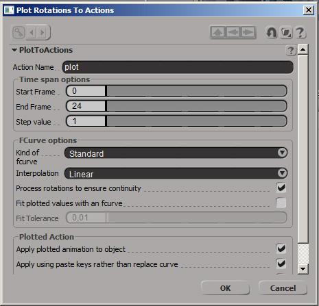
Here you can set start frame (mostly 0) to end frame and the step (set it to 1)
You may set the interpolation to Linear, if you like to work like me. It will set the animation curve to a linear curve between the keyframes. Then press OK.
Second Step:
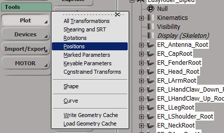
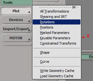
Deselect all. Then select the members of the group which contains the bones.
Use Plot Rotations in the Animation Toolbar
The PPT will appear again, set the start frame, end frame and step and press OK again.
Now all roots and bones have keyframes for every frame.
We do not need the controller-hierarchy anymore. Delete it, hasta la vista baby. Delete the UpVectors as well, if they are not a part of the controller hierarchy.
Now there should be the same movement of the rig like the one with the controller rig.
We are ready for export into a .smd file now.
Part 8: Exporting the Model and Animation ready for Compiling
To compile a complete character with one animation you need a minimum of three .smd-files
A) The "Model" itself, containing the mesh and texturing data as well the refered name of the texture picture
B) The Collision Model or Physbox which provides the collision detection.
This model has to be merged into one polygon mesh as well and has to be enveloped with our rig.
C) The Skeletal Animation with the keyframe data.
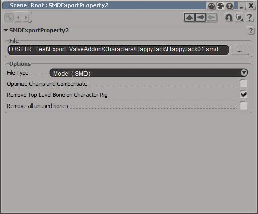
There are three check buttons at the bottom the export property page.
In my case i only checked Remove Top-Level Bone on Character-mesh
Result: It kept the top-level bone. Logic?! But it worked fine so let's keep this check button on and uncheck the other two. This has to be kept constantly for all types of .smd-files.
You may test what will happen when you check one or all three and open the .smd after that:
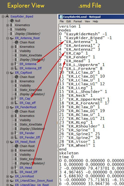
If you look at the right column you see that there are 0 "EasyRiderMesh" -1 to 29 "ER_Wheel"
While EasyRiderMesh is the Mesh file, ER_Wheel is a bone
The order of the first rows in the smd-Files has to be the same like in the figure below.
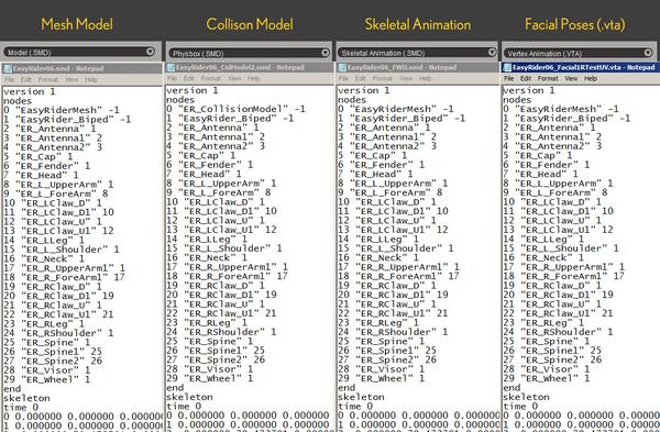
BTW: the numbers behind the names of th ebones indicate the parent ID.
For more information about .smd-files look at
Developer.valvesoftware.com under Studiomdl Data
With this smd-files you can start compiling now. Have a ton of carots!
Part 9: Troubleshooting
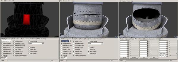
Part 9.1: Normals and Shading weird
If your shading in the ModelViewer of the sdk looks like in the figure below and the normals are errected upright it might be possible that the transformation values was not resetted or freezed.
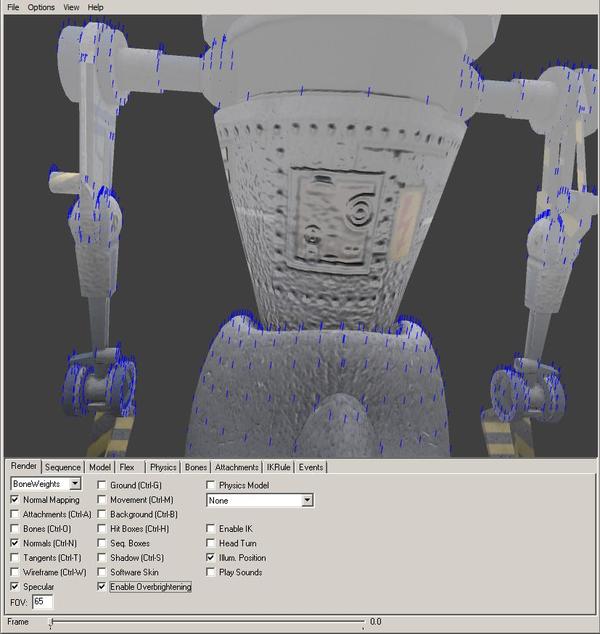
Use Freeze All Transforms under Transform, then repeat enveloping, plotting and exporting.
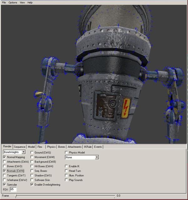
The result should look like this, the normals do not point in a single direction and the shading looks better now.
Part 9.2: Bad Vertex Data
There is already a forum's note about my problem with Bad Vertex Data.
Interlopers.net
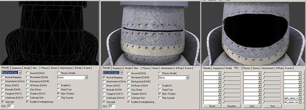
The reason why the polygons are marked red in the ModelViewer of the sdk might be bad
UV-Data. It happened when I added facial animations on it. A redesign of the mouth area and a retexturing fixed the problem. Unfortunately, all the enveloping had to be done again. But because the rig construction was well so far, I did not spend a century on this.
Part 9.3 Problems writing during export
Check if you have the right to overwrite/access the content in the folder you like to fill with data.
Select the folder and use the right button of the mouse. Go down in the menu to "Properties".
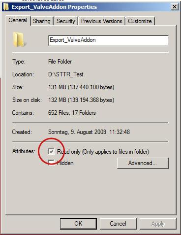
This window will appear. Uncheck the button "Read only" and let's proceed this for all subfolders.
Part 10: Conclusion DOs and DON'Ts
1.Only work with models which are finished and set to the right size.
2.Generally prevent many hierarchy levels on skeletons. The hierarchy of a rig is build by the controller-hierarchy.
3.For rig elements do not use models. Only bones or nulls are recognized by the export-addon.
4.Set Roots, but do not rotate roots. Rotation values of roots must be 0 0 0.
5.Don't scale bones or roots. Scaling values must be 1 1 1.
6.User UpVectors when bones "overrotate" or rotate on a weird way like flipping over an axis.
7.Plot roots and top-null first, only Translation.
8.Plot then bones, only Rotation.
9.Then delete all controllers and Upvectors.
10.Check the animation again, if weird rotation occurs,
set more UpVectors to the flipping bones or check the enveloping.
11.If the animation is OK, export them as Skeleton Animation
Appendix
Sources
Tim Kitevski:
"Practical Guide to Facial Animation for the Source-Engine"
Tim-Kitevski_Personal-Project_Practical.pdf
Valve Developer Wiki
www.interlopers.net
Noesis Interactive: Character Design Integration with Half-Life® 2
Noesis Interactive: Modifying Source Characters
Noesis Interactive: Advanced Character Animation for Source Games
Links to more tutorials
Developer.valvesoftware.com
Interlopers.net
Noesisinteractive.com
Design3.com
Xsifiles.com
Miscellaneous Links about Steam, Tracks, Trouble & Riddles
Animationdesign.de peegee's portfolio
Moddb.com home of the mod
Sttr.forumotion.net the mod's forum
Youtube.com Demo One on YouTube
Youtube.com Character Introduction on YouTube
Comments to this tutorial or questions?
pgrafdesign [at) web [dot} de
Controller Rig Creator V1
The JScript you need to create the controller hierarchy.
// S.T.T. & R. Advanced Rigging Tutorial
// JScript Script of Controller Rig Creator V1
// for Autodesk(TM) Softimage(TM) Mod Tool
// by peegee June 19th 2011
// This jscript will create a controller rig for selected skeletons.
// Some groups will be created to make later selections easier.
// Just select the skeleton (or the entire scene) and hit the run button.
//
// The Controller rig will consist of spheres to pick and rotate
// and constrainer nulls which controls the bones.
// Only rotate the spheres called "Controller".
// -------------------------------------------------
var oRoot = Application.ActiveSceneRoot;
var roots = new ActiveXObject("XSI.Collection");
var bones = new ActiveXObject("XSI.Collection");
roots.Unique = true;
bones.Unique = true;
//Check the selection for roots and bones and sorting
for(var i=0;i<selection.count;i++)
{
if(selection(i).type=="root")
roots.Add(selection(i));
else if(selection(i).type == "bone")
{
var kine = false;
try
{
kine = selection(i).kinematics;
}catch(e){}
if(kine)
bones.Add(selection(i));
}
}
if(roots.count == 0)
{
logmessage("No chain roots selected!",siError);
}
else if(bones.count == 0)
{
logmessage("No chain bones selected!",siError);
}
else
// Creation of null for highest position in hierarachy
oRigChief = Application.ActiveSceneRoot.AddPrimitive( "Null", "ControllerRig" );
{
// Group roots
SICreateGroup( "Controller", null)
SICreateGroup( "Roots", null);
SIAddToGroup( "Roots", roots, null );
// Group bones
SICreateGroup( "Constrainer", null);
SICreateGroup( "EnvelopeBones", null);
SIAddToGroup( "EnvelopeBones", bones, null );
// Controller Spheres Creation
for(var j=0;j<roots.count;j++)
{
// Creation of spheres for roots
var rootpose = roots(j).Kinematics.Global.Transform ;
oSphereR = oRoot.AddGeometry( "Sphere", "NurbsSurface", "rootcontrol" );
var oGeometryParams = GetValue( oSphereR + ".surfmsh.geom" ).Parameters
oGeometryParams("subdivu").Value = 4 ;
oGeometryParams("subdivv").Value = 2 ;
var oGeometryParams2 = GetValue( oSphereR + ".sphere" ).Parameters
oGeometryParams2("radius").Value = 1 ;
oSphereR.Kinematics.Global.Transform = rootpose;
// Contraining the roots to the spheres
SIApplyCns( "Position", roots(j), oSphereR, null );
// Adding Sphere to group
SIAddToGroup( "Controller", oSphereR, null )
var oRootChild = roots(j).FindChildren();
var oCurrentBone = roots(j).FindChild()
var bc = 0 // Counter Bones Reset
// Parsing the Skeletons for bones
for(var k=0;k<oRootChild.count-1;k++)
{
if (oCurrentBone.type == "bone")
{
var bc = bc + 1;
if (bc > 1)
{var oSphereN = oSphere;
}
//Ceate a null , position it at the bone
var bonepose = oCurrentBone.Kinematics.Global.Transform ;
oNull = oCurrentBone.AddPrimitive( "Null", "constrainer" );
oNull.Kinematics.Global.Transform = bonepose ;
//Contrain the bone in "Orientation" mode to the null
SIApplyCns( "Orientation", oCurrentBone, oNull, null );
SIAddToGroup( "Constrainer", oNull, null )
//Create a surfmesh sphere, position it at the bone
oSphere = oRoot.AddGeometry( "Sphere", "NurbsSurface", "bonecontrol" );
var oGeometryParamsB = GetValue( oSphere + ".surfmsh.geom" ).Parameters
oGeometryParamsB("subdivu").Value = 4 ;
oGeometryParamsB("subdivv").Value = 2 ;
var oGeometryParams2B = GetValue( oSphere + ".sphere" ).Parameters
oGeometryParams2B("radius").Value = 0.75 ;
oSphere.Kinematics.Global.Transform = bonepose;
SIAddToGroup( "Controller", oSphere, null )
oSphere.AddChild(oNull)
var oCurrentBone = oCurrentBone.FindChild();
// hierarchy creation of the controller rig spheres
if (bc <= 1)
{oSphereR.AddChild(oSphere);
}
else
{
oSphereN.AddChild(oSphere);
}
}
}
LogMessage("Aznzahl der Bones ist " + bc);
// Adding the root controller Sphere to the overall null
oRigChief.AddChild(oSphereR)
}
}
//End of Script
Wow, this is intense. To think you do this all for free, you guys are so generous.
This looks like a great tutorial. I wish it was for 3ds. But I'm sure parts of it will be helpful to me.
Thanks.
@jokerme Invest some time into XSI i use a few packages and ive found it the easiest by far :P
Concerning the tutorial man WOW... What more can i say Wow great job very well laid out, clear concise and to the point Well done.
Easiest one is the one you know :P
hehe true but i know Max and Sketchup fairly well :P
This comment is currently awaiting admin approval, join now to view.