


Contents
- The basics and models exporting
- Material editor sweep-through
- Textures
- Importing your models into the game through the Material editor
- Creating assemblies
- Materials setup
- LOD, rendering distance system and bounding sphere
- Adding collision meshes
- Engine configuration
- Derelict assembly
- Ship schematics and icons
Hey all, this tutorial will cover all the basics for preparing, exporting and importing your meshes into the game engine, setting up Levels of detail, managing collisions, particle effects and all other elements required for a ship to function properly in game. We will not cover the modelling and texturing itself, but will start from the prepared meshes from there on. Regarding modelling and file formats, you can work in 3dsMax or Blender, our importer will handle their exported OBJ files without problems, and for texturing any 2D software should do it as long as the software in question supports .dds file formats. For this tutorial, we will use our Exemplar gunship class, you can download mesh files and textures below.
As an introduction, here’s a quick recap of all of controllable ship classes in Starpoint Gemini Warlords, their default sizes and turret numbers.
- Gunship Size: 3,5 Turrets: 2-4
- Corvette Size: 7,0 Turrets: 4-6
- Frigate Size: 20 Turrets: 8-10
- Destroyer Size: 25 Turrets: 10-12
- Cruiser Size: 40 Turrets: 13-16
- Battleship Size: 65 Turrets: 17-21
- Dreadnought Size: 110 Turrets: 28-32
- Carrier Size: 150 Turrets: 24-28
- Freighter Size: 15 Turrets: 2-3
- Freightliner Size: 60 Turrets: 4-5
We tend to keep polycount up to around 30 000 tris, of course it all depends on the ship class itself, bigger the ship class, higher the polycount.
1. The basics and models exporting
 To start off, if you look at Image 1, you see a 3dsMax viewport with all the needed meshes. With this tutorial comes the OBJ, FBX and Max files for you to download and are at your disposal to test out the workflow and check the meshes in your 3D software for yourself as you read through the tutorial. We will work on the “Exemplar” gunship class here with its hull length approximately 3,5 Max Generic Units. Open a 3d model of the Exemplar that came with tutorial files. So, let’s go through meshes one at a time.
- First you have the main mesh(es). Here you can see that a ship is made of more than one objects, each object having its own material assigned to it. This is not mandatory however, you can have the entire BASE MESH made in one OBJECT, depending on your own needs and workflow. If you do model the ship with more objects and separate materials, simply keep in mind to have the pivots of all the objects on the same coordinates before exporting the meshes. Our Exemplar here is made of 7 separate objects, with a few of hull plating meshes/materials, lights, engines polys, decals. Engines Polys and decals are on a separate meshes because they will use different SHADERS when importing into the game. This also helps with deactivating certain meshes/objects when configuring LOD levels later on etc.
- Next are 3 LOD levels (Level of detail). If you open the 3d model file, you’ll see that certain objects are not here with more LODs (Decals, Lights for instance) since we’ll simply switch off their rendering later through the MaterialEditor at a certain distance. So, at LOD 1 you can see we’ve got prepared 4 models with lower polycount, and we continue doing so till LOD3. Keep in mind that pivots are mandatory to be set at the same coordinates as the base mesh.
- Concave collision mesh. This is a single mesh used for detecting a weapon’s hit in game engine. It is lightweight, simplified as much as possible.
- Convex collision meshes. This is a set of 4 CONVEX meshes in this particular case, with pivots at the same coordinates as the base mesh. These are not attached since they have to remain convex at all times and are exported individually and are used later on as collision meshes when crashing into other objects etc.
- Derelict mesh spawns in game when a ship in question is destroyed. In our case, here it will use the same collisions as the base ship since it’s not all that different.
Now we got all the meshes needed and pivots prepped at the exact same location, it is time to start exporting the objects. It is usually a good practice to have the objects and LOD levels named appropriately so it’s easier to export and find the files after you’re done with modelling and texturing.
Now, I’ll UNGROUP and position all the meshes on 0,0,0 and convert them all to Editable meshes. Time to Export all the meshes with a setup seen in Image 01. You can export them one at a time or use a batch exporter for a quicker result. Be sure to remember where you exported your files ;). Now we have exported all of 25 OBJ files and have them readied for importing.
2. Material editor sweep-through
Before we continue with models importing and materials part of the tutorial, it is time to check the MaterialEditor you can find in your Root game directory. Through this toolset you can import meshes, setup materials, make particle effects, combine assemblies, set turrets on your ship files etc. But let’s start with the basics.
In your game root directory, you can find the MaterialEditor.exe and MaterialEditorConfiguration.cfg file which you can open in notepad and setup a desired resolution among other things.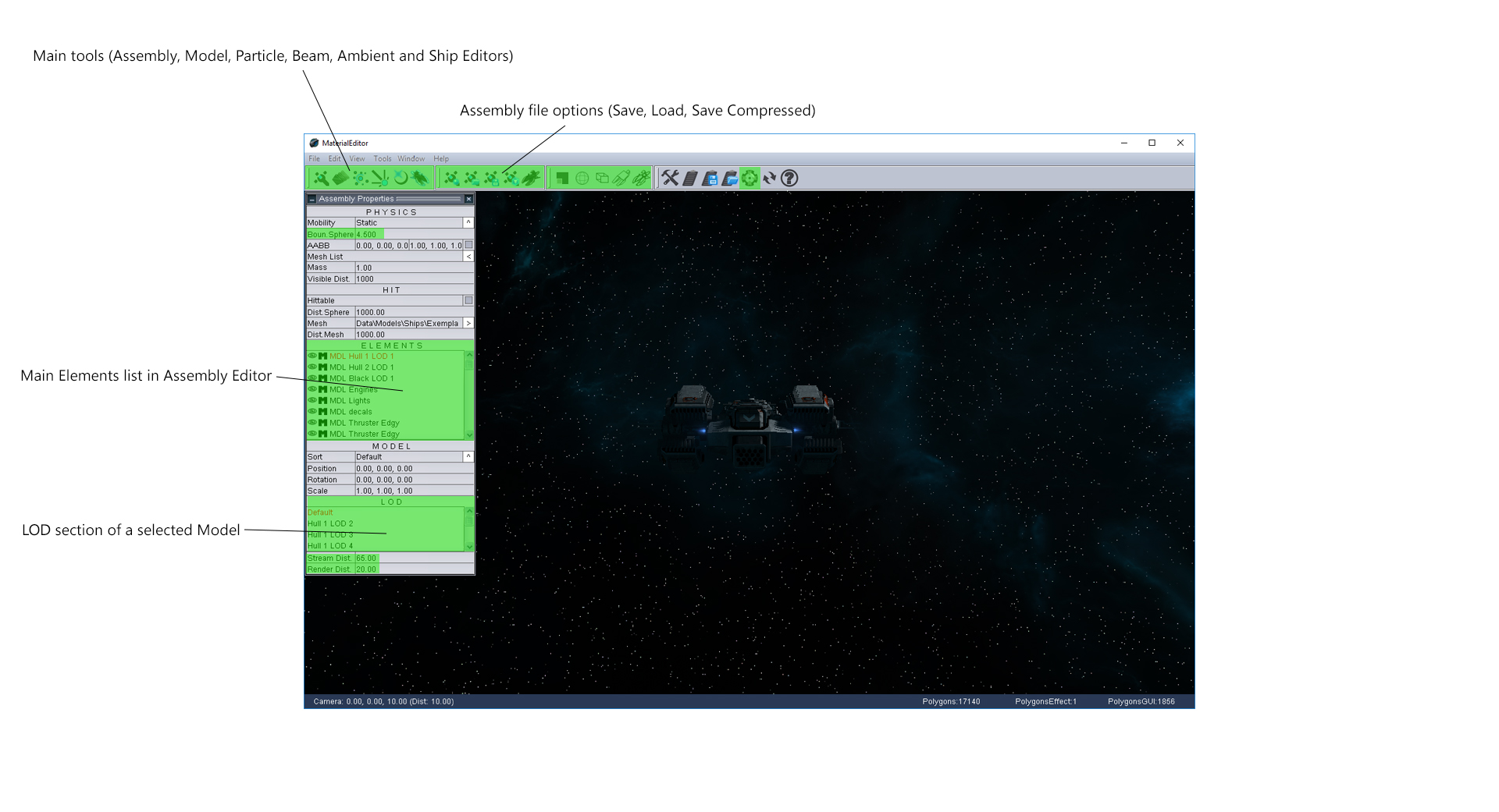
When you launch the MaterialEditor.exe you’ll see the screen as seen on Image 2. Upon launching, the Editor loads the Exemplar ship as default, but don’t worry, for tutorial purposes, we’ll duplicate this ship and go through the entire creation process again. When MaterialEditor is launched, it’s default “TAB” is ASSEMBLY EDITOR (the first option in Main tools sections as shown on Image 2. Assembly Editor is actually a CONTAINER of sorts for all the meshes, particle effects, LOD levels, collisions.
Next in line in Main tools is the MODEL EDITOR. Here you can find all the material parameters, from shader choice to textures setup, self-illumination properties etc. Following MaterialEditor comes the PARTICLE EDITOR through which you can setup your particle emitter and its properties.
Now, we’ll jump over to the last tool in Main Tools section and go select SHIP EDITOR which will be needed to complete the ship creation process. Here you can setup the number and arc of a turret per each battery. We’ll go through each of these sections more thoroughly a bit later, so do not worry if there are some questions still opened.
3. Textures
Make sure you’ve downloaded the Exemplar tutorial files with 3d objects and textures before we proceed with this portion of tutorial. You will also need a 2D editing software. We at LGM Games use Photoshop and following nVidia plugins I recommend you download and install. Here you have Normal map filters and more importantly dds exporter, a texture format we use in SGW. Look for the exporter on the nVidia website. In Starpoint Gemini Warlords we commonly use 3 textures in a single material, a Diffuse (Diff), Normal (Norm) and Special (Spec) texture. Check Image 3 for a quick overview. The format used is .dds 8.8.8.8 ARGB 32 bpp with MipMaps optional.
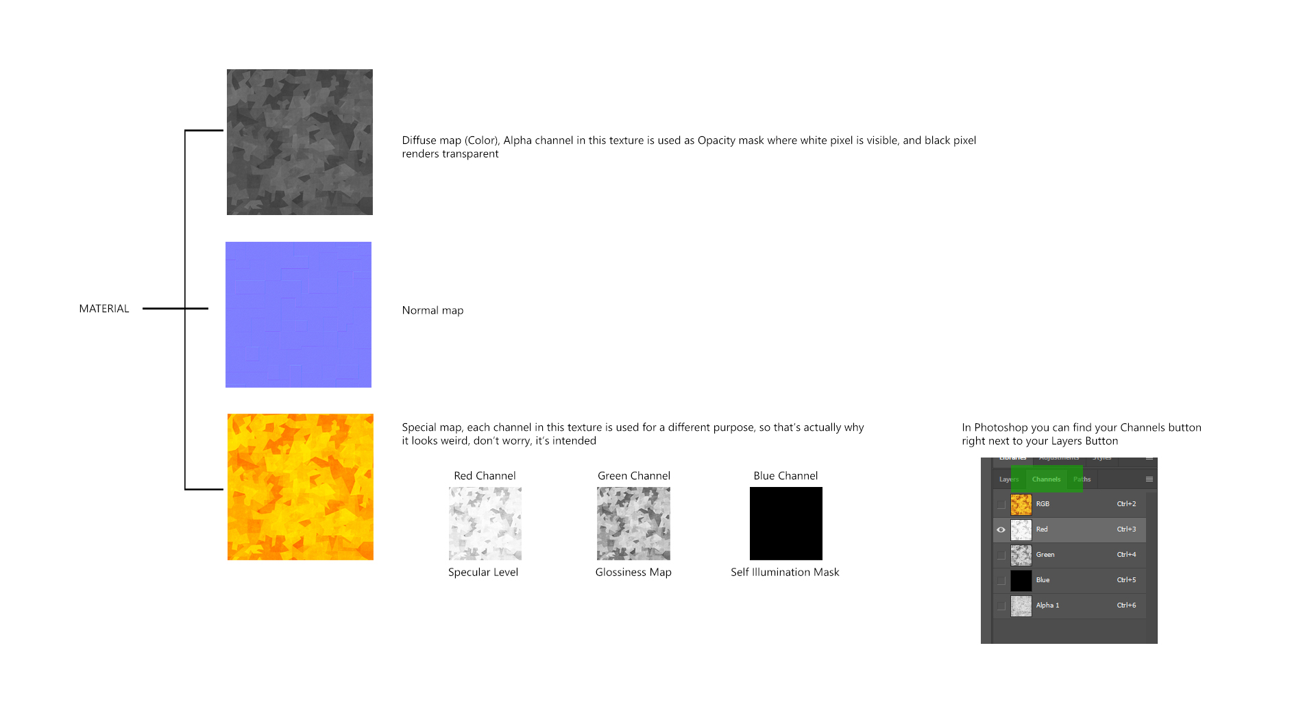 So, first is a Diffuse Map, or Color map, which is quite self-explanatory. The only important note here however is that Alpha Channel in this texture represents the Opacity mask with a black pixel being a transparent one. Normal map is also a standard texture, baked or generated. Special map is a bit different. If you check the Metal1Spec.dds you’ll see it looks all weird and yellow. Do not worry about it, it looks that way because every Channel in this texture represents a different map.
- Red Channel is used as a Specular level map
- Green Channel is used as Glossiness map
- Blue Channel is used as Self Illumination mask, where a white pixel lets that particular pixel from a Diffuse map to render with self-illumination and glow.
On Image 3 you can see where you can find the Channels tab in your Photoshop.
4. Importing your models into the game through the Material editor
Now we’ve gone through the basics of Material editor and textures, it is time to finally start importing your models into the game. By now, you should be having all 25 OBJ files, and your textures (from a download link). Open your game root directory and navigate to Data\Models\Ships\ Here create a new folder “ExemplarTutorial” and paste all of your OBJ and texture files (.dds files) into it.
Once you’re done, launch the MaterialEditor.exe in your game root directory. Don’t worry about a default Exemplar being loaded. Open your Model Editor tab. Once opened the Model Editor tab, you get the Model file options such as Import New model, load and save Whale model, save compressed and save collision whale model. With all of the options mentioned being self-explanatory, the last button (Save collision whale model) is quite important since unlike saving usual models, collision meshes are saved via this option because you do not want the collision mesh to render as visible, and as such you do not need the UV coordinates etc. So use this button only to save the collision files (in our case 01,02,03,04 and COLShot.obj files).
On the Model Editor tab, click the Import New model button and navigate to your Data\Models\Ships\ExemplarTutorial\ Now you should see all OBJ files in this folder. Import each file and save each accordingly as Whale model, or as a Collision whale model depending on which file you’re importing. Simply import and save each one as .mdl file. Don’t mind all files rendering as black, will manage the materials a bit later. With that done you’ve got 25 .mdl files as seen on. Time to start assembling these models into one entity.
5. Creating assemblies
Launch the MaterialEditor.exe. The default opened tab is the Assembly Editor. In the upper toolbar, click on New Assembly button to empty the current assembly file of all the elements.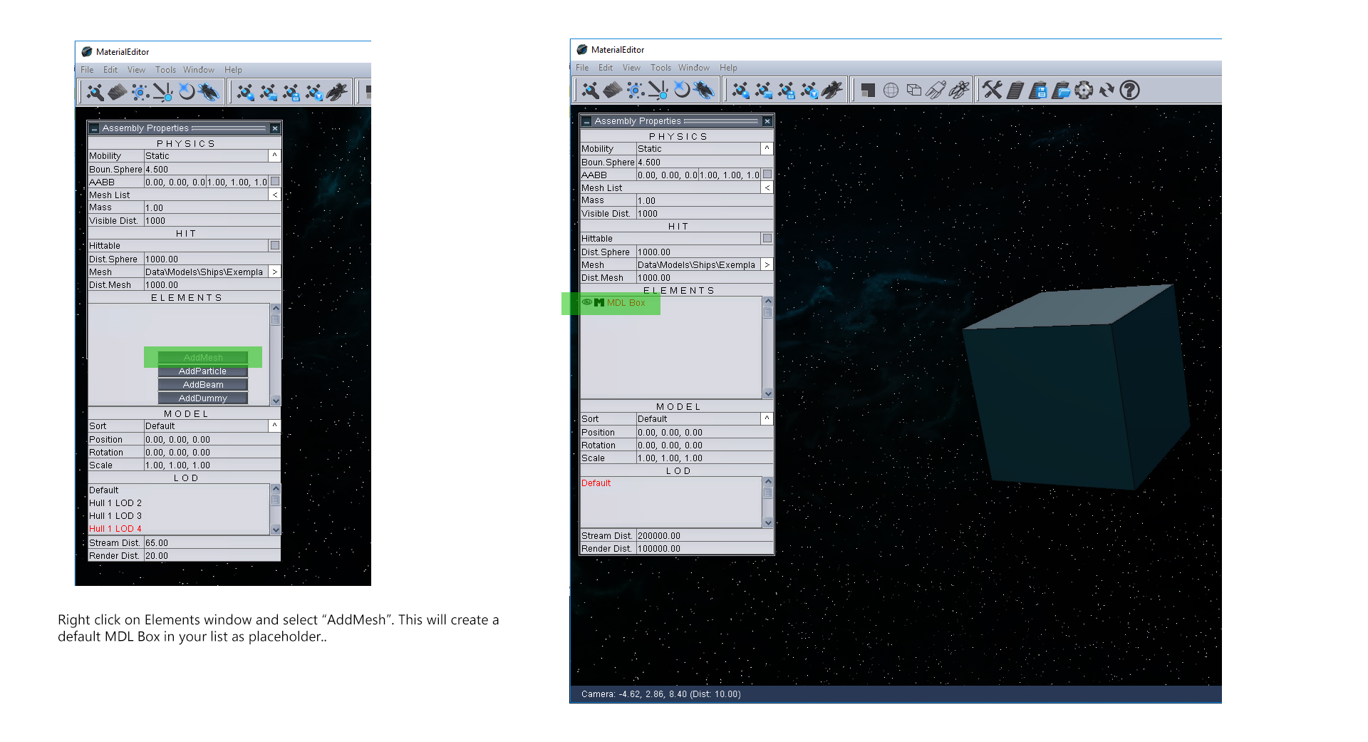 Next right-click on the Elements window (Image 4) and in drop down menu choose “AddMesh”. This action will create a simple box model as a placeholder. With MDL Box selected in your list, select the Model Editor tab in the upper left corner.
This action will open the properties of your model from the Elements list (in this case still named MDL Box). With Load Whale Model option navigate and load your .mdl file to switch the MDL Box model with thee needed part of your ship. In our case, the first model is “Attacheable.mdl”.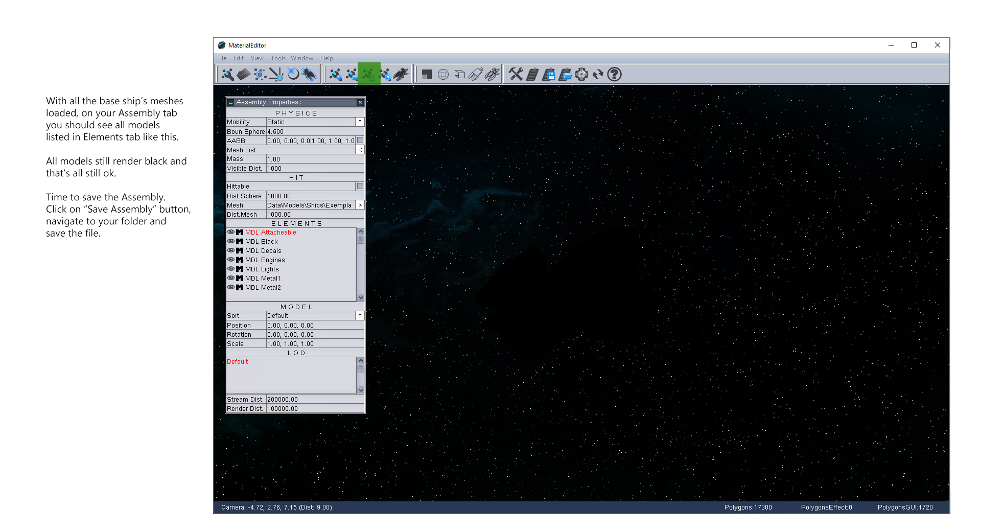
Go back to your Assembly tab, add another mesh, and through Model Editor tab replace the newly added box model with another part of your ship. Repeat procedure with all of your base meshes. Leave LOD levels/meshes and collisions for later.
When you’re done, you should have the following meshes in your Elements list: Attachable, Black, Decals, Engines, Lights, Metal1 and Metal2 (Image 5). Save the Assembly file in your ship’s directory. In our case, we’ll name the assembly ExemplarTutorial.asb.
6. Materials setup
Now we got 7 models assembled in one file. All the models have a black material at the moment and it’s about time we make proper shaders and textures on them.
Launch the Material Editor and on Assembly Editor tab, load the ExemplarTutorial.asb. Let’s say we want to setup the Metal1 material first. On your Elements list select the MDL Metal1 and open the Model Editor tab. First thing we want to do on this tab is to check if the right shader for our model is loaded in. We want the spg_pbr_shader.fx to be set here. If you need any other shader, click on the icon next to the shader’s name and navigate to Data\Shaders\PBR\. Here you can choose a desired shader.
In a section a bit below, you choose your model’s textures. For “Metal1” load all three textures you’ve downloaded with our tutorial files (Metal1Diff.dds, Metal1Norm.dds and Metal1Spec.dds), each one in its appropriate container. If you cannot see any textures in your ExemplarTutorial folder, make sure you’ve got the files in the folder to begin with and when trying to open, check “All files” option. With shader and textures loaded in, you can now setup the basic parameters such as Normal scale, Glossiness, Specular level, Self-Illumination etc.
When done with parameters setup don’t forget to resave the file (Metal1.mdl) so you don’t lose your changes. The procedure is almost the same for all the models. The only difference more or less are different parameters for each desired model. For instance, we want Decals.mdl to render with transparent parts with no shadow casting and for Lights.mdl we want to have illumination and glow etc. Have in mind that you can always have an entire ship or any other model made as one mesh, with one texture set and LOD levels.
Engines polys are the only mesh that is supposed to be detached and imported as separate because it has one more functionality added later for the gameplay and visuals (engines will be tagged to glow brighter faster the ship flies). Now we’ve got all the base models and materials (except for Engines) configured and saved.
7. LOD, rendering distance system and bounding sphere
When modelling your ship, station or any other model for that matter, depending on your polycount you might want a few of LOD levels prepared and configured. We’ve already imported our LOD levels for our Exemplar ship, have them in our ExemplarTutorial folder and now only need to assign them to our base models.
Open the MaterialEditor and load the ExemplarTutorial.asb. Let’s configure LOD levels and rendering distances for Metal1 part of the ship. In your Elements list select MDL Metal1. You’ll notice a LOD section a bit below with listed “Default” tag, designating your main mesh (and the one with the highest polycount). Right-click in the section and from drop down menu select “AddLOD”. Navigate to your ExemplarTutorial folder and open Metal1_LOD1.mdl file. Use the same way to add all 3 LOD levels to the list. Now you can assign the material from Default mesh on each LOD level by right-clicking on each LOD level and using CopyMaterial option. This will copy and paste the entire base material and its properties to a LOD level you’ve selected. Repeat the procedure for all the models that have their LOD meshes (Metal1, Metal2, Black, Attachable) and when done, save changes to assembly.
With all LODs loaded in and material configured, now is a good time to setup RENDERING and STREAMING distances of all the meshes and their levels of detail. For each model and LOD you can setup these parameters right below the LOD list section. Stream Distance stands for a range the model will start to load in, while the render distance naturally stands for a range from camera the mesh will start to render on screen. Take your time to setup these and test it out in the editor itself to make the transitions as smooth as possible. In case of Exemplar here, you can even switch the entire parts off at a certain distance (Lights and Decals for example). You can monitor your distance and triangle count at the bottom of the Material Editor screen as you zoom in and out your camera.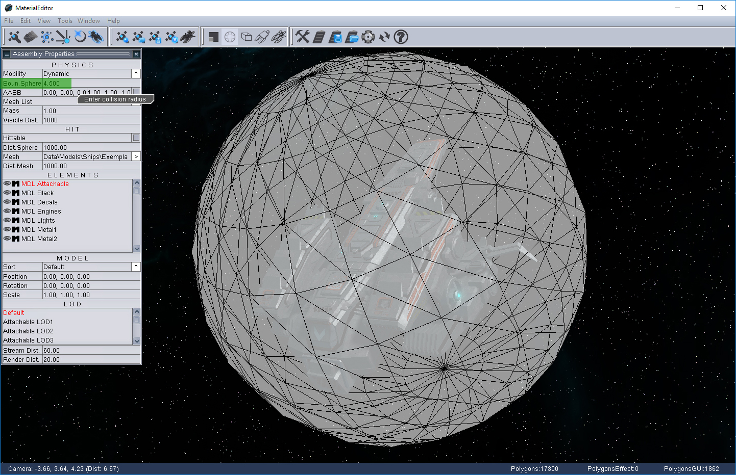
Now would also be a good time to setup the Bounding Sphere of your ship (Image 6). This sphere is an important part of any model’s setup as it greatly optimizes the framerate. With it try to encompass the entire assembly keeping no parts of the assembly out of it, but also do not leave to much of “free” space around it. This sphere has two important functions. Primarily it serves as a low-cost checkpoint if the assembly should render on screen in the first place. If the sphere’s vertices are not on screen, then the entire assembly will be discarded in rendering procedures for that frame.
A second functionality of the sphere is optimizing To-Hit calculations during combat. To simplify, in massive combats, it’s expected to have a great number of flying projectiles and hitting calculations in each frame. Using this sphere, every projectile that doesn’t enter the bounding sphere will be discarded calculations-wise for that certain frame. On the other hand, for every projectile that is indeed inside the bounding sphere the engine starts calculating weather the projectile hits the assembly’s To-Hit collision (ColShot.mdl) and deals damage.
8. Adding collision meshes
Remember the 5 collision meshes we’ve imported few steps back and saved as Collision Whale Models? It is time to explain them a bit more and attach them to our assembly file. First of all, we have two types of collisions meshes, each type used for different purposes:
- Collision used for To-Hit Calculations (we usually name it ColShot.mdl). Here we’re talking about a single greatly optimized mesh that is used in calculations if the assembly has been hit with a weapon or not. It is usually best to create a new object that will tightly encompass your ship or any other object you’re modelling. This mesh does not need texturing as it will not render visible in game (Saving as Collision Whale model removes UV mapping coordinates and Material from the file).
- Collision/s used for calculating if two objects collide or crash with one another. An important note here is that this mesh needs to be CONVEX for PhysX to work properly. Depending on how accurate you want these meshes to be you may need more than one mesh to encompass the entire assembly. Be wary if using more than one mesh, attaching them together will ruin their convexity, so remember to keep an eye on their pivots and export them separately (in our tutorial files, I’ve named them 01 – 04.mdl). For more information about concave vs. convex meshes check the following link on rustycode.com
In part 04. of this tutorial, we’ve already imported collision meshes and saved them as collision models in ExemplarTutorial directory. Time to attach them within the assembly file.
Open “ExemplarTutorial.asb” with Notepad or Notepad++ and scroll to the end of the file. At the end you’ll see a “Waypoint” data chunk. You’ll be adding collisions right above that chunk with paths to your models the following way:
CollisionMesh:
{
 MeshName: Data\Models\Ships\ExemplarTutorial\ColShot.mdl
}
ConvexCollisionMeshes:
 {
 MeshName: Data\Models\Ships\ExemplarTutorial\1.mdl
 MeshName: Data\Models\Ships\ExemplarTutorial\2.mdl
 MeshName: Data\Models\Ships\ExemplarTutorial\3.mdl
 MeshName: Data\Models\Ships\ExemplarTutorial\4.mdl
}
 As seen above, in CollisionMesh chunk you add your single mesh for To-Hit calculations and in ConvexCollisionMeshes chunk you add paths to your convex meshes used for crashing into stuff. When done, save the file.
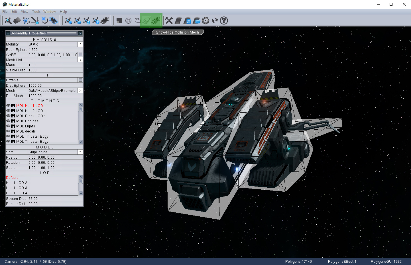
You can check if collision meshes are all well positioned in MaterialEditor, Assembly Editor Tab with Show/Hide Collision and Show/Hide Hit Mesh options as shown on Image 7. If collision meshes have an offset, you might want to check the position and pivots of those meshes prior the exporting phase.
9. Engine configuration
In this stage of tutorial, we’ll handle the last remaining model linked in our assembly, Engines.mdl. This model should be separately imported into the game as it will have a different shader and material than the rest of the assembly. We’ll set them up so they can glow brighter when a ship is at full speed.
In our Exemplar.asb we already have the attached Engines.mdl since 05. part of the tutorial. First, we have to change the Material of the .mdl file in question. Let’s do this through the notepad this time. Navigate to Data\Models\Ships\ExemplarTutorial\ and open Engines.mdl. Replace the entire Material data chunk with the following one:
Material:
{
  Shader: XYZNTUV Data\Shaders\spg_engine_shader.fx
  Texture:
  {
    Name: Data\Models\Ships\Thrusters\Engine_1_Diffuse.dds
    Slot: 0
    Type: FromFile
  }
  Texture:
  {
    Name: Data\Models\Ships\Thrusters\Engine_1_Diffuse.dds
    Slot: 1
    Type: FromFile
  }
  Texture:
  {
    Name: Data\Models\Ships\Thrusters\Engine_1_Spec.dds
    Slot: 2
    Type: FromFile
  }
  DiffuseColor: 0.10 0.40 0.98 1.00
  Speclevel: 3.0000
  Glossiness: 60.0000
  AlphaTestTreshold: 0.2000
  DiffuseFresnelMult: 0.0000
  AmbientMultiplier: 2.0000
  AmbientBias: 0.1500
  SIMapMult: 7.4500
  SILevel: 0.0000
  FresnelPower: 1.0000
  FresnelBias: 0.7000
  FresnelMult: 2.5000
  HalfLambertPower: 4.0000
  ShadowCast: 1
  ShadowAccept: 1
  DepthMode: 0
  ExtraTexture: -1
  MinTessDistance: 20.0000
  MaxTessDistance: 200.0000
  DisplacementStrength: 1.0000
  DisplacementOffset: 0.5000
  MaxTessFactor: 0.0000
  Param6: 0.0000
  Param7: 0.0000
  TessSampleTextureMode: 0
  pbrNormalScale: 0.0000
  pbrSpecularLevel: 0.0000
  pbrGlossiness: 0.0000
  pbrGlossMapPower: 0.0100
  pbrGlossMapOffset: 0.0000
  pbrDiffuseReflect: 0.0000
  pbrLightMapMult: 1.0000
  RasterizerMode: 1
  BlendMode: 1
}
Once Material is replaced, save the file. The last thing to do is “tagging” this model to behave like thrusters in game. Open your ExemplarTutorial.asb and find “StaticMesh” chunk where Engines.mdl is linked. Here the only thing you have to do is replace the DEFAULT AdditionalSort with SHIPENGINE tag. Once done whole chunk should look like this:
StaticMesh:
{
 Instanced: 0
 MeshName: Data\Models\Ships\ExemplarTutorial\Engines.mdl
 Position: 0.00 0.00 0.00
 Rotation: 0.00 0.00 0.00
 AngularVelocity: 0.00 0.00 0.00
 StreamDistance: 800.00
 DrawDistance: 400.00
 AditionalSort: SHIPENGINE
 Scale: 1.00 1.00 1.00
}
Once replaced, save the file. With this action, we conclude this part of the tutorial. Your meshes and materials, LOD levels, collisions, bounding sphere, rendering distances are all assembled and configured. The assembly is ready for further additions like particle systems, upgraded thruster visuals etc.
10. Derelict assembly
In Starpoint Gemini Warlords, every ship when destroyed has a chance to leave a derelict behind. At this time we already have Derelict.mdl in ExemplarTutorial folder since the 04. part of tutorial (models importing phase).
This particular model must have its own assembly file, so let’s launch MaterialEditor.exe and create a new clean Assembly. Add a new mesh and load in Derelict.mdl file. Setup the material with needed shader (spg_pbr_shader.fx) and textures (DerelictDiff, DerelictNorm and DerelictSpec). Save the model as Derelict.mdl, and assembly file as Derelict.asb. Since our Derelict mesh looks nearly similar to a full base mesh, we shall use and link the collisions models from our ExemplarTutorial.asb. Copy and paste collisions chunks from the original file to your derelict.asb. Of course, if you model a quite different derelict mesh than the original mesh, you would probably do better if making and linking specific new collisions for a Derelict.asb.
With model and assembly completed, we have to link it with the Exemplar ship in order for it to spawn after destruction. Navigate to Data\Models\Derelicts\. Here you will find folders for all ships available in game. In each folder, there is a file wreck.der. These files contain base preferences and scripts that trigger in game, and also a path to a designated derelict assembly file. In Data\Models\Derelicts\ create a new folder named ExemplarTutorial, and copy-paste any wreck.der file mentioned into it. Open the added file in Notepad and change the ModelName path to lead to your Derelict.asb file like this:
ModelName: Data\Models\Ships\ExemplarTutorial\Derelict.asbOnce done, save the file. Now we have to link the created .der file in our database. A note here, it might be helpful if editing any database to use Excel for it might give you a better overview of the file (If using Excel, remember to Format Cells as Text to avoid any auto-corrections that might corrupt the file). Navigate to Data\Base\ and open EditorDerelicts.wdt file in Notepad/Notepad++. Here you simply add one more line that will lead to your .der file. You have to add a unique ID, unique KEYNAME and of course a valid path to your file like. Save the file. Now we’ve got a full package set for a derelict assembly to spawn after the ship’s destruction.
11. Ship schematics and icons
In Starpoint Gemini Warlords, every ship has her set of schematics images that show up in game when reviewing a ship before purchasing, comparing to other ships etc. Among downloaded tutorial files you can find these files by names schemL.dds and schemT.dds. If you haven’t already, copy them to ExemplarTutorial directory.
 Those two images are either renders of your 3D objects or remastered screenshots from the MaterialEditor. Resolutions of these images are 256x256px saved as 8.8.8.8. ARGB like any other texture with saved Opacity map in Alpha channel because we do not want the background to be seen in-game.
Before linking the schematics images in your database, you will also need your ship’s icon which will be used in the game during browsing ship’s list among other things. We usually make this icon out of SchemL image. Required resolution for an icon is 52x52px with alpha channel (opacity). This icon will not stand as an individual file though. Navigate to Data\Icons\ and open ShipIconsSmall.dds in your Photoshop.
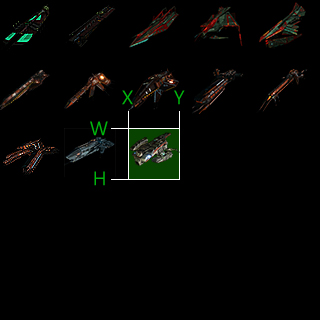
Here you will see icons of all the available ships positioned in a 64x64px grid (you can setup your 64px grid in PS by opening EDIT – PREFERENCES – GUIDES, GRIDS & SLICES and setting Gridline every 64px). Use grid as a helper only, the icons are still 52px in size. Now place your icon to follow the pattern and remember to setup the Alpha Channel as it is always used as an Opacity map.
When done, save the file as dds 8.8.8.8. ARGB as usual. With ship’s schematics and Icons texture setup done, it’s time to link them to ship’s database.
Navigate to Data\Base\ and open Ships.wdt file in your Notepad/Notepad++. Like in any other database, you’ll need to add another line with your unique ID and unique KEYNAME, and add paths that lead to your ship’s schematics files (SchemT and SchemL columns). Since in Warlords we have dynamic databases, when you’re about to assemble your mod, in your ships.wdt file (database), you will only have one line in it that implements ExemplarTutorial to the game. Give it ID 0 and unique tags as stated and the game will cross reference and take into account all the changes to any of your databases. You can learn more about how dynamic databases work in Warlords in a separate tutorial.
We also need to write in the coordinates for the engine to know where your ship’s Icon is placed on ShipIconsSmall.dds texture (Columns IconX, IconY, IconW and IconH). See Image 8 to see which coordinate goes to which column. Once done, save the file.
With this we conclude this part of the tutorial. We will continue to a next phase of ship creation, Particle systems, tweaking ship’s engines, setting the ship’s parameters in .shp files etc.
For further information, please feel free to contact us: modding@starpointgemini.com
For more information about SG Warlords check out these links:
Starpoint Gemini Warlords homepage
Starpoint Gemini Warlords forum
Starpoint Gemini Warlords Steam store page
LGM Games dev-blog
Follow us on Facebook
Follow us on Twitter


That's ... huge work to write these tutorials. Perfect, I like it :)
This comment is currently awaiting admin approval, join now to view.
This comment is currently awaiting admin approval, join now to view.