| Posts | ||
|---|---|---|
| RoadWorks need some help. | Locked | |
| Thread Options | ||
|
|
Apr 2 2012 Anchor | |
|
Currently using 3ds Max, I have built roadworks in different parts so I can Target weld them together.
My main problem with the target welding is that if is that I'm having trouble finding the best way to approach it. The corners of my roads were designed with angles with one sided angles to get easy angles that can be easily used to help make symetry to make crossover roads but the angles won't link with other roads on both sides of the roads due to the fact that there wouldn't be enough polys to reach both angles. Currently I'm trying to make sure my roads more structured, was trying to base them using careful road structures like this:
At the moment this project is a long project for me to do since trying to structure Salt Lake City right but the problem is getting the roads to look right first even if its at a basic structure. Also this will hopefully help with me future project at Moddb.com. Edited by: Ronnie42 |
||
|
|
Apr 6 2012 Anchor | |
|
I find it very hard to understand your english here and I dont really see a problem. As long as you remove all the unnecessary geometry those road modules should link together just fine. And if you dont know what I mean by that just do this: delete all vertices that are in the middle of those planes - they dont shape the meshes and therefore are not needed. Two vertices and one edge per side is all you really need - then it wont be a problem welding those pieces together as they have the same width. The 90 degree curved road for example only requires 32 vertices to remain its current shape: one for each corner (4) and 28 for the pavement-meets-road geometry. Edited by: Nightshade |
||
|
|
Apr 6 2012 Anchor | |
|
Firstly sorry about my english. (Have personal reasons for that) Anyway the target wield is pretty easy for me but was trying to connect the main roads to the corners and the crossroads. The problem was that the angles should connect to each road but is limited since I can't use the same poly twice for target wielding. Just to be clear I'm refering to the poly used on the corners of the pavements of the turnings/crossroads to help connect the pavements. Originally used this video:
|
||
|
|
Apr 6 2012 Anchor | |
|
"The problem was that the angles should connect to each road but is limited since I can't use the same poly twice for target wielding." I don't understand this part in bold. Maybe you are using some incorrect terminology. When you say angles, are you refering to edges on the mesh? The sides of those modules looks symmetrical to me, meaning it shouldn't really matter what way you turn these road pieces. They should weld together just fine no matter what "direction" they are at. Maybe you should draw a picture and point out the problem areas when trying to weld. Might make it easier for us (or well... -me- ) to understand this problem. Because as I see it now, there shouldn't be a problem merging/welding together those modules. AND/OR you could save your meshes in the OBJ-file format, upload it to speedyshare and I could take a look at them. Anyway, may I ask why you want to weld/merge these modules together in the first place? If you want these pieces to be modular then shouldn't they be independent meshes? Edited by: Nightshade |
||
|
|
Apr 6 2012 Anchor | |
|
Yes edges are probably a better way to explain it. Well I was trying to weld these together so I create a vast network of roads for a city, seemed like a simple thing to do. The video link suggested using the modular roads in this way since it would mean I could create unique parts of roads, make any changes I wanted anywhere in the roadwork. Yes the symmetry looks right on the crossovers but the polys on the edges aren't usable for poly welding since the polys would need to reach one road but won't be able to be re-used for the other roads in each direction. An example is if I had roadabout with 4 directions then only 2 directions would be able to be used since the edges have only 1 poly per edge. Anyway hope that makes more sense. |
||
|
|
Apr 6 2012 Anchor | |
|
Yea it's nothing wrong about the video - it's teaching you the proper ways of art asset making for level design: modular is the way to go. |
||
|
|
Apr 6 2012 Anchor | |
|
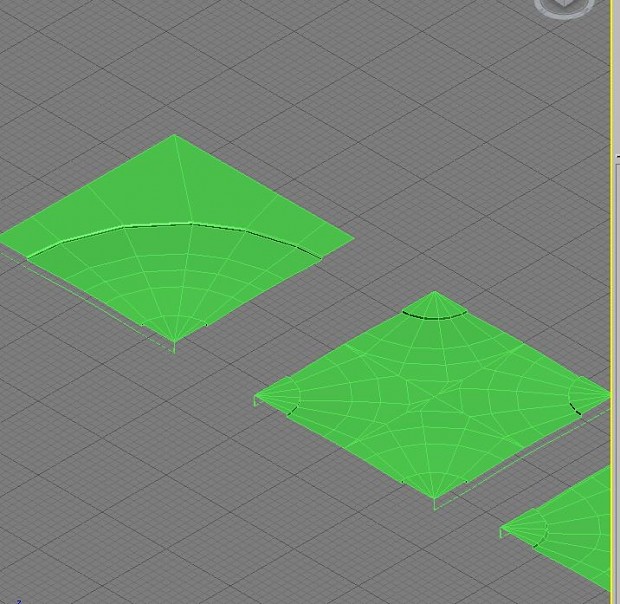
Below shows the wireframe from a sample of my work. To the left it shows 1 straight road fully connected to a possible turning. This turning has edges like the one on the right image. If you look at the right image you'll notice that if I used that edge to target weld then I won't be able to re-use that edge to target weld to the other road. (This method could have also been used if I was going to make a roundabout)
|
||
|
|
Apr 7 2012 Anchor | |
|
Correct me if I'm wrong but when you do this "target weld" (I'm a maya user so im not familiar with the 3ds max -terminology) does the entire edge move in order to link up with other meshes or does just the vertex move forward? (growing the edge till one of it's vertices link up with another vertex). Because as it look right now, your road modules have their edges skewed - they are not straight, not running parallell to edges they should run in parallell with, etc. And this could be due to this target welding. Take a look at this picture: In Maya, the way you merge together meshes is that you first select both meshes, then merge them with a "combine" command, and then you merge all the vertices that lie on top of each other with a "merge vertices" command. Edited by: Nightshade |
||
|
|
Apr 7 2012 Anchor | |
|
Barely understand what you meant but the circles you mentioned aren't much of a problem since the parellells can easily be cleaned up, some of the parallells look different due to the pavement. The circle in the middle column is the straight paths connected to the cross road section on the left image. While if you look to the right image the one circled should connect to the middle edge and the other corner to the left would also connected to the middle edge but this won't work since the poly would have been used by either bottom edges. Edited by: Ronnie42 |
||
|
|
Apr 8 2012 Anchor | |
|
|
Apr 10 2012 Anchor | |
|
The way I was mapping seemed to take too long and was getting confusing so I changed my plans. Decided to use splines instead, using these video's. Basically I set the splines to a setting 3000 width to make sure the splines getting ported correctly into Udk. Using splines would mean I can make all sorts of shapes for my designs. Anyway if anyones got any further questions or feedback let me know. Also noticed Udk graphic problem: 3ds Max: Udk imported: Edited by: Ronnie42 |
||


Only registered members can share their thoughts. So come on! Join the community today (totally free - or sign in with your social account on the right) and join in the conversation.